Category Archives: RepRap 3D Printer

Assembly and evaluation of the QU-BD MBE 1.75mm Filament Extruder for 3D printers

3D printer head 1.75mm filament extruder

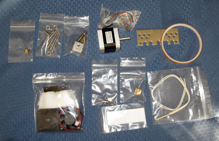
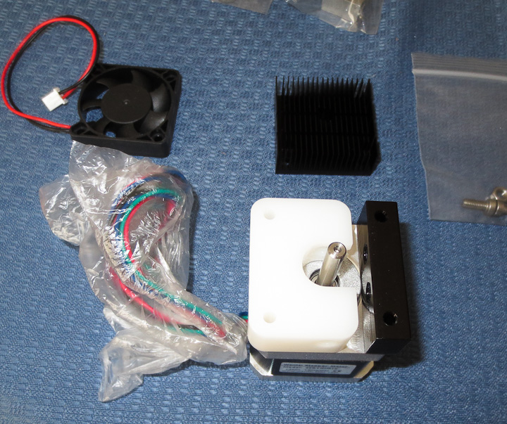
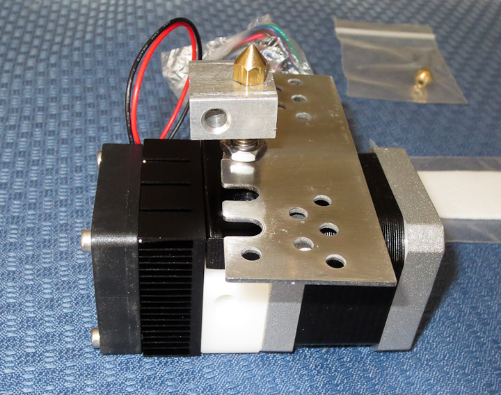
If you haven’t seen my earlier posts, I’m building a 3D printer, roughly modeled after the RepRap Prusa and RepRap Mendel designs but considerably larger.   In an earlier post I shared my own 3mm filament stepstruder plastic extruding 3D print head design and photos showing progress on its development.   While searching the interweb for nozzles to purchase, I came across the QU-BD website with 3D printer supplies.  Given the low cost (starting at $34, $63 all decked out with bullet heater and stepper motor) of this 3d printer extruder, one was ordered on the spot.  It was as received as you see in the above photo.  All of the parts were nicely segregated into plastic bags.

3D printer head by QU-BD

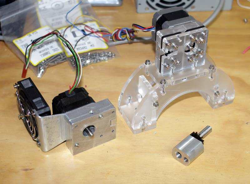
The first step was to tear into the packages and examine the parts.  The design is simple and well thought out.  It uses a combination of off the shelf components and custom machined pieces.  I really like the modified heat sink and small fan.  These two parts will also  be used on the 3mm filament print head of my own design as well.

3d Printer head assembly MBE v9

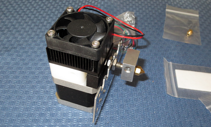
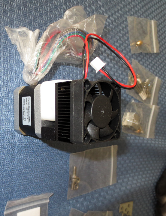
Assembly instructions are available on the QU-BD website here  or available on my site saved as a pdf here.  The above shows the body of the 1.75mm filament plastic stepstruder  on the NEMA 17 stepper motor that came with the kit.  Here is the data sheet for the Wantai 42BYGH610 stepper motor included in the QU-BD MBE V9 3d printer extruder kit.

3d printer head stepper extruder   d printer head stepper extruder

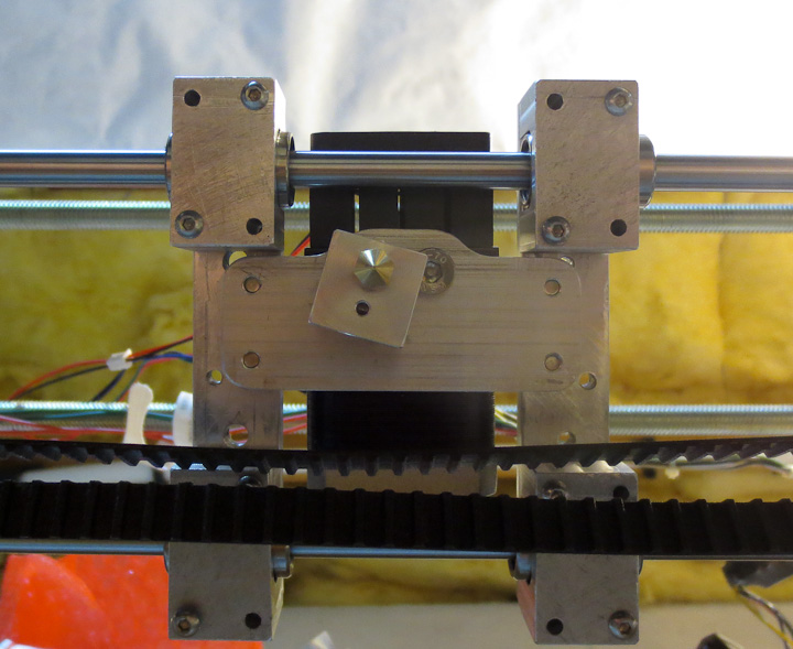
The kit assembled relatively easily.  All of the parts were well machined with the exception of the aluminum rectangular heater block.  The M6 threading was drilled and tapped at a slight angle (~5 degrees).  The result was that the nozzle did not sit flush against the block when tightened in place.  In the photo below you can see the misaligned angle of the heater block in relation to the body of the stepper motor and extruder.

3D printer head by QU-BD

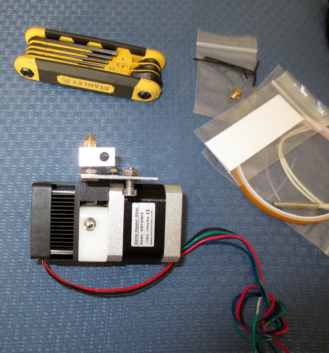
I felt this minor issue was not worth the hassle of calling and complaining to QU-BD.  In fact given the price of the kit, and the DIY nature of product, issues like this are to be expected.  Some quick machining on the lathe squared the faces up to the M6 threaded through hole correcting the problem.

3D printer head by QU-BDA

The overall design of this 1.75mm filament stepper based extruder 3d print head is well thought out. The parts are all well made with the exception of the heater block.  The only piece that I felt was not useful in this kit was the included mounting plate.  This part will not  be used in my printer build but I suppose it is bolt in for some of the popular DIY 3D printer projects available in kit form.

3D printer head by QU-BD

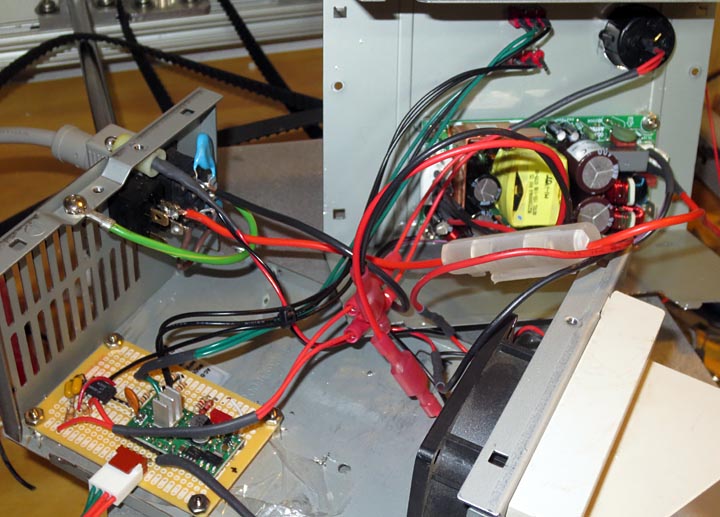
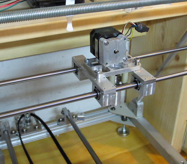
In the above photo you can see my mounting plate. Because of the much shorter hot end/nozzle portion on this 1.75mm filament plastic stepstruder I needed to drop the entire head as close as possible to the linear shafts that make up the x axis on my 3d printer build.  I machined a 0.150″ drop into the mounting plate. This gets the nozzle down almost  well below the timing belt and linear bearing mounts.

3D printer head by QU-BD

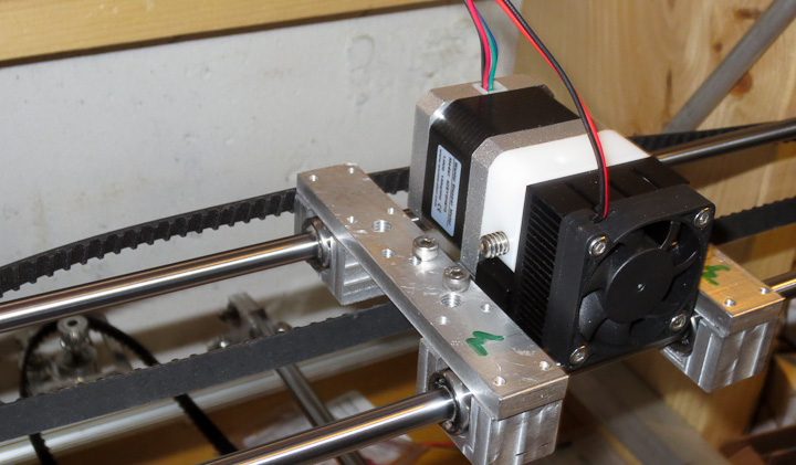
Here is the QU-BD MBE v9 Extruder in place installed on my 3d printer.  It is small, looks good, and fits well with the rest of the machine.  As of now my printer has mounts for 2 different print heads.  Eventually I’ll settle on one or the other and machine new bearing supports (the aluminum rectangles with the green M’s on them) to reduce mass as much as possible.  Less mass means less inertia resulting in faster print head movement.  The plan is to redo the bearing mounts as well when it is fully operational.  They will be produced by printing them out in ABS, thus having the machine produce upgrade parts for itself.


A cheap stepper motor drive based on a 555 and pololu A4988 stepper driver

A4988 Stepper motor drive

As I near completion on my 3D printer build, I found myself needing a way to drive stepper motors to quickly test axis motion (watch the video at the end of this post).  To that end I threw together this low cost stepper motor drive.  It is based on a Pololu A4988 stepper motor driver being run by a 555 timer set up as an oscillator.  I wanted something cheap that I could quickly throw together to test the motion on the axis as well as keep handy for future stepper motor projects. I spent a little more time on this project then it warranted but now I have a great little stepper motor drive for testing future projects.

Circuit to drive a pololu a4988 with a 555 timer

The circuit diagram above shows the basic schematics for the stepper motor drive. Sorry about the chicken scratches on paper version, but all the info is there if you want to make one of these for yourself.  As always if you have any questions shoot me an email at:  zac AT projectsbyzac.com  The 555 timer is run as an astabile oscillator to generate the step pulses to drive the Pololu A4988 stepper driver (A4988 data sheet is here) & (Pololu A4988 datasheet is here) .  If you’ve read my previous post on building a cnc machine control box based on Pololu 4988’s you know I love these little stepper drive boards. They are similar to stepstiks (drop in pin for pin replacements in fact) which will eventually run the 3d printer on the RAMPS electronics which just arrived.  There are newer drop in higher performance Pololu models available now but I had a A4988 green boards on hand.  To allow for variable motor speed control I used a 10 turn 10K potentiometer inline in the 555 circuit.  This allows the drive speed to be varied by turning the knob.  The pot I used has a digital read out.  When I find a speed that works well to test a particular motor/axis drive, I can easily set it in the same speed in the future.  Thanks to Adam Perkins for these 10 turn pots. I traded him some parts a few years back for a few of these 10 turn pots with read outs. This is the first project on which I have used one of them.  He has a very useful webpage with great info on electronics and is my electonic project mentor from my UNH Days.

The circuit is soldered up on a small board from Radio shack.  I’ve housed the entire project in an old PC power supply case.  I love using PC power supply cases for projects and always have a couple on hand in my parts inventory.  They have good cross flow cooling, built in fan, switch and power cords making them the perfect project enclosure.  The pololu A4988 can handle up to 2.0 A with a heat sink and air flow for cooling which the power supply case fan supplies.  To power this project I initially used a spare 12v 2.0A wall wart installed. The supply was noisy and it was affecting the stepper motor drive output.  Additionally when it was driving the motors I could hear the cooling fan speed decrease, so it wasn’t up to the current draw needs of the motors being tested.  I changed over to an Astec LPS50-M Series 60 Watts power supply I had on my parts shelf.  This supply could easily handle the motor load and would provide a clean 15 volts,  the supply used was an Astec LPS54-M (datasheet for the LPS54M powersupply is here).

Pololu based stepper control unit in pc power supply case

The above photo shows the finished product.  I used my CNC machine to mill out the top of the case for the pot with the readout and drill holes for mounting the power supply and the 2 toggle switches.  One switch controls the direction of the motor (dir pin #14 on the pololu) and the other interrupts the signal between the 555 oscillator and the step pin (pn #13 on the pololu) allowing to start and stop the stepper motor without powering down the controller.

The above video shows the driver being used to test the Z axis on the 3D printer. I have the current control way down so when raising the axis the motors struggle a bit (the sound you hear changes from the smooth driving on the way down).  I thought some of you might enjoy the video clip. There will be more videos as the printer is further tested now that I made a youtube account to host them.


DIY 3D Printer Progress

reprap based 3d printer x axis design

About a year ago I started building a 3D printer based on the RepRap 3D printer community. Progress essentially stopped with the arrival of spring (aka adventure season), but it is once again project season (aka winter).  My 3D printer build is approaching the testing phase for axis motion, print head extrusion quality and laying down my first builds.  This post will show the progress and provide some thoughts on the design of my 3D printer.

3D model of plastistruder cross section   Plastistruder design based on Makerbot design

Last winter I had worked out a rough design for my own plastistruder 3D print head, I made a first go at my own design but felt I could do a better job.  I had set the x axis such that it would mount a plate with 1.5″ on center bolts allowing me to experiment with different print head designs by having them be modular and easily swapped out.  The above renderings show my current design for a 3mm filament plastic extruder.  Based off the MK6 extruder from makerbot (that they apparently no longer support or sell), it was designed to use the same nozzles and 40W 12v cartridge heater.

3d printer x axis with plastic extruder head mounted

Above you can see I’ve finished the x axis mounts.  They are functional but had any weight reduction done to them yet.  The mounting plate and heat break/hot end side are done.  I plant to machine down a pc heat sink to mount to the body of the extruder opposite the NEMA 17 stepper that will drive the filament into the hot end and out the extrusion nozzle.   I found online a great little 1.75mm extruder head that I purchased here at a company called QU-BD and have ordered one since they are so cheap. I will test out both of them and compare results in a future post.

3d printer - reprap based Z-axis and x axis drive motors.    Pololu based stepper drive circuit to for 3d printer axis motion testing

The Z axis design in my printer is basically two steppers driving threaded shafts from the same stepper pulse signal.  This seems to work well and has been done in other reprap 3d printer designs.   I am doing basic motion testing of the axis with a 555 timer as a pulse generator to drive a pololu A4988 stepper driver board.  These are great little boards for running steppers and I have used them in other projects like my cnc control box.  It’s a crude set up but does not require having a computer dedicated to this thing yet.

Reprap 3d printer progress

What’s left to get this thing running?  I need to order some new LX series timing belts the correct size for both the y and x axis.  Build  a y axis chassis that is lighter then the solid aluminum test plate you see in the above pictures and then mount my larger heated build surface.  Then it will be another round of electronics headaches.  Hopefully this time the supplier for my reprap electronics board doesn’t send me junk.  See my earlier post for my problems with the first Gen 6 electronics I ordered.    Then it will finally be time for testing and printing parts.  I already have a list of things to print out a mile long.  Several friends want me to print them out the standard rep rap parts. I plan to help them out. Everyone should have their own 3d printer at home.

Assembling a Makerbot Mk6 Stepstruder

stepstruder mk6 compared with my cnc machined plastistruder

The reprap 3D printer project has been on hold while I work on other more critical items like upgrading the cnc machine and the holiday rush. I’ve got some pretty awesome friends who help me out with projects.   This Makerbot Mk6 stepstruder was cut by one of my very good friends who happens to have access to a laser cutter at work.  I supplied some acrylic and delrin sheet.   When he had some time he stayed late after work to cut them out for me.  Laser cut parts are a thing of beauty, especially in the frosted acrylic as there is a nice contrast between the crystal clear sides and frosted faces.  Sadly I forgot to take pictures during assembly so here’s a link to the makerbot assembly instructions.  I need to get a small digital camera for the shop area for project documentation.  I promise to get better with this in the future.


The Makerbot Mk6 extruder is an elegant design. I really like the use of captive nuts and m3 screws to hold it all together.  For final assembly I will use acrylic adhesive.   I need to order and make a few parts for this unit.  I plan on running it side by side on the bench with my cnc unit.  Experimentation when they are both complete will determine which is a better print head / plastistruder for my 3d printer.   I realize that I will need to do some significant lightening of the CNC plastistruder I designed to compete with the mk6 stepstruder in terms of mass/inertia.

The picture above shows the “filament” going through the plastistruder.   The print head for the Reprap style 3D printers is basically a micro sized extruder for molten plastic.   A plastic wire, is fed through a sharply cogged pulley (missing in the pic) into a hot nozzle/head unit (the aluminum bit down bottom).    Continually feeding the hard unmelted filament into the tightly fitting tube causes pressure to rise and the molten plastic to be extruded through the nozzle on the bottom (also not shown, use your imagination please).   The computer will control the rate of extrusion and match it to the speed at which the printer is moving to produce a uniform printed layer of plastic.  That’s the basic idea behind the Reprap based print heads.  They have undergone a continual evolutionary improvement and will continue to do so into the future.  I love the open sourced community nature of Reprap development.  You get parallel and divergent development as different people work on their own units and try different things out.