Category Archives: RepRap 3D Printer

The basics of 3D printing explained in pictures (or how parts are made on a 3d printer)

reprap based large 3d printer

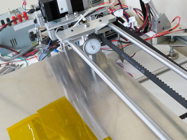
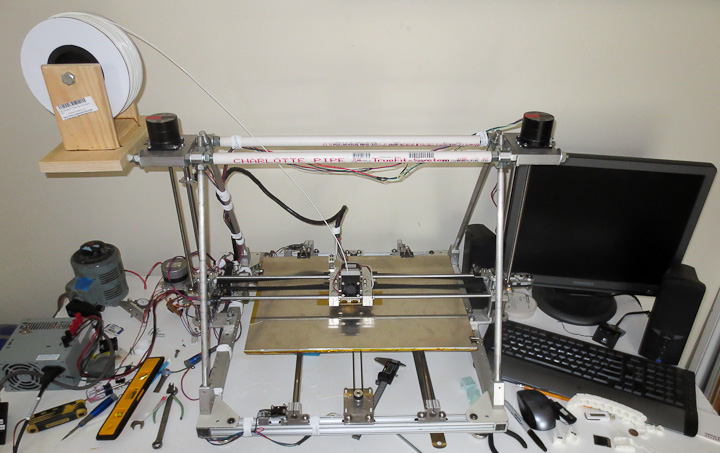
While hiking up in the White Mountains with friends this past weekend I started talking about my 3D printer project (shown in the photo above).  One of my hiking companion responded with, “So how does 3D printing actually work?  I get that it makes things, but not the how.”  This post aims to show you, in a series of time lapse photos, how my FDM type 3D printer builds a part.    I took this series of photos throughout the printing of a pair of cable chain links.  The images go in order from top to bottom and left to right.  Take a look and you will see the white ABS plastic growing up from the build platform as the build progresses.    The layers are 0.3mm tall in this build and there are 45 layers in total.  It took about 40 minutes to print these parts start to finish.

Time lapse photos of 3d printing-7270   Time lapse photos of 3d printing-7273

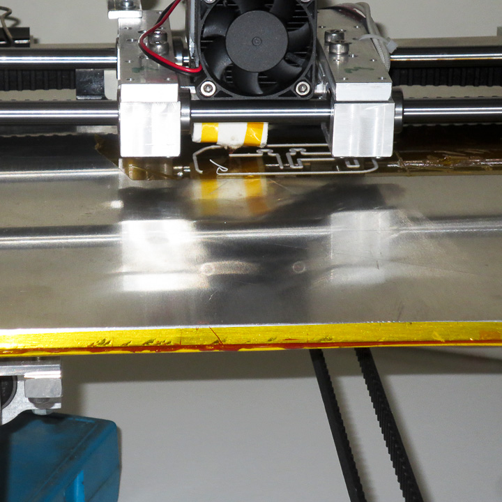
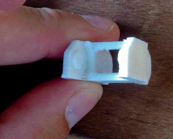
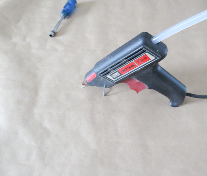
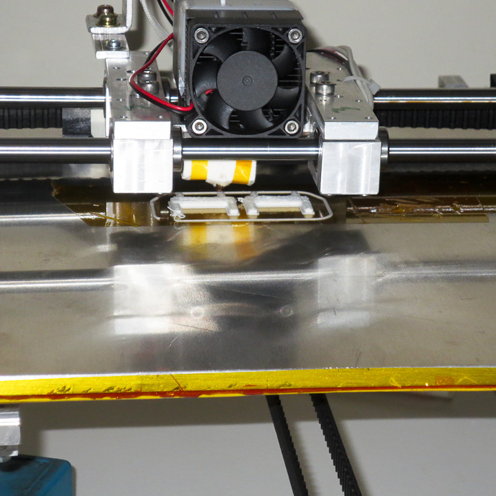
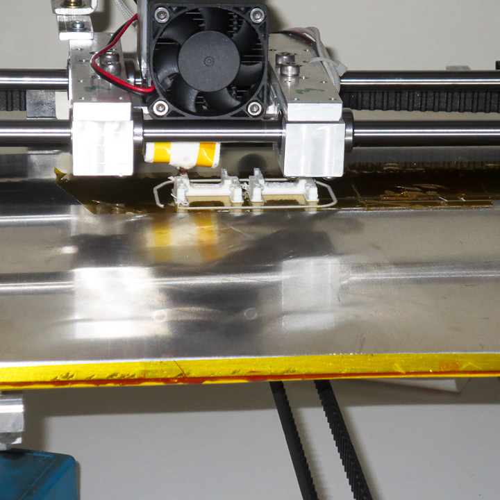
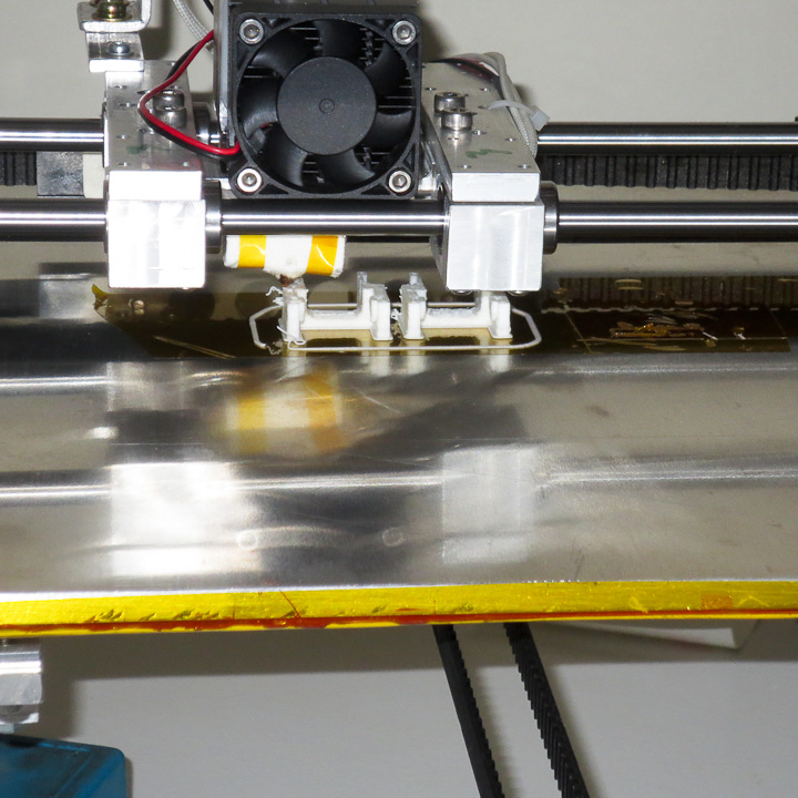
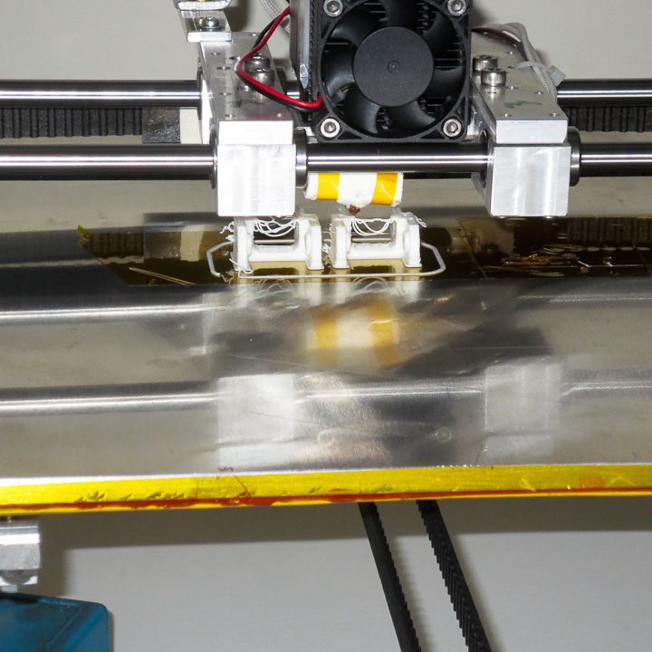
The first image (above left) shows the outlines of the first layer being put down on the build platform.  The print head (or plastistruder) works a bit like a tiny hot melt glue gun, melting the plastic filament and squeezing out a tiny thin layer through a nozzle onto the solid surface.  The second image (above right) shows the outline filled in on the left part.

Time lapse photos of 3d printing-7278   Time lapse photos of 3d printing-7279

After filling in the first layer the print head is raised up 0.3mm and it prints a second layer on top of the first.  This printing layer on top of layer is fundamentally how all 3D printers produce parts and is often referred to as Additive Manufacturing.

Time lapse photos of 3d printing-7281   Time lapse photos of 3d printing-7282

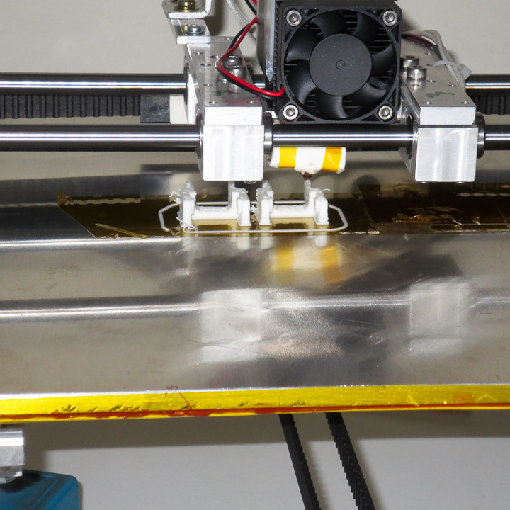
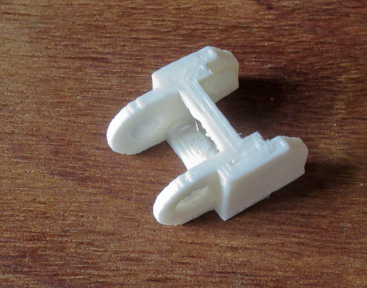
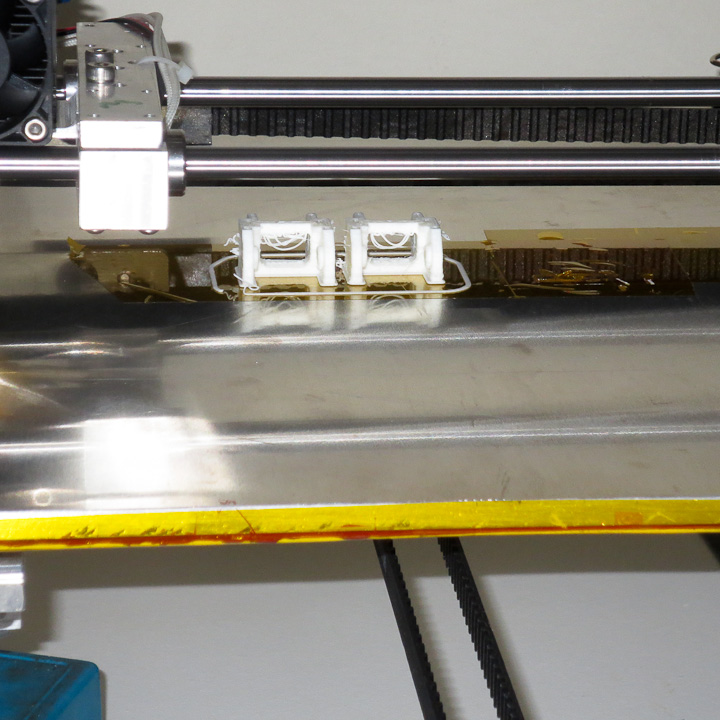
The printer continues to deposit layer on top of layer. 

Time lapse photos of 3d printing-7286   Time lapse photos of 3d printing-7287

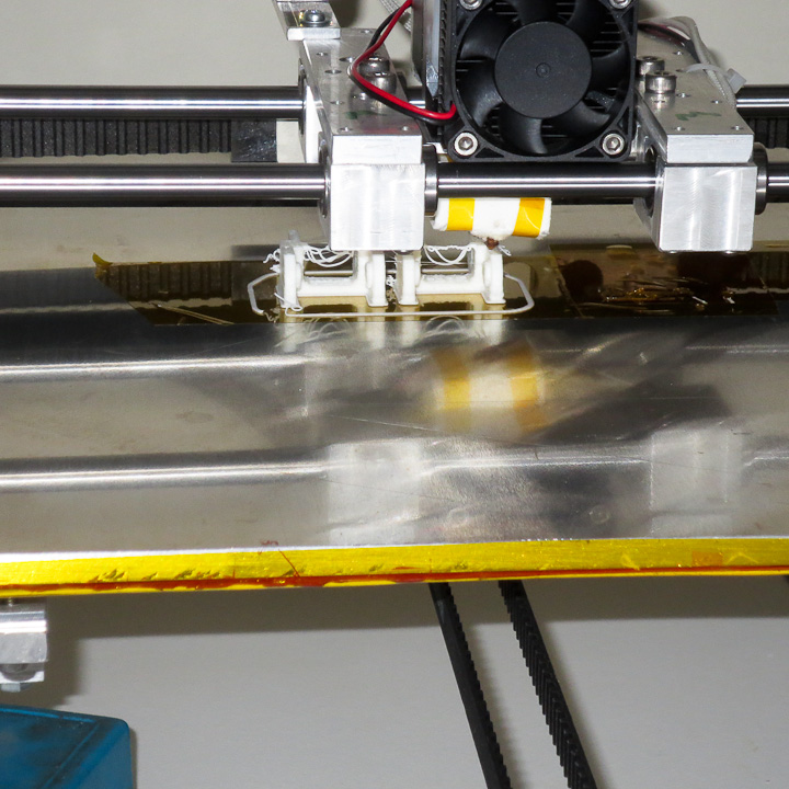
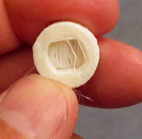
This particular cable chain link was printed without support material.  You can see the plastic sagged and drooped down in the unsupported area as the printer reached the top of the part.  In subsequent printing of this part,  I tested different support options.  The addition of computer generated support features (small towers or thin square wave walls)  eliminate the sagging issue.  The support material is removed readily when the part is done printing with the assistance of a small screw driver or hobby knife.   Eventually I plan to install a second print head so I can use a water soluble plastic support that will dissolve away after printing. This will allow me to print  finer more complicated geometries.

Time lapse photos of 3d printing-7299

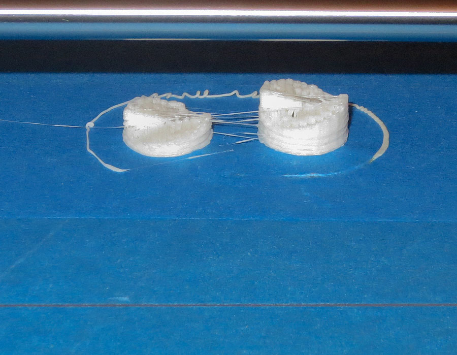
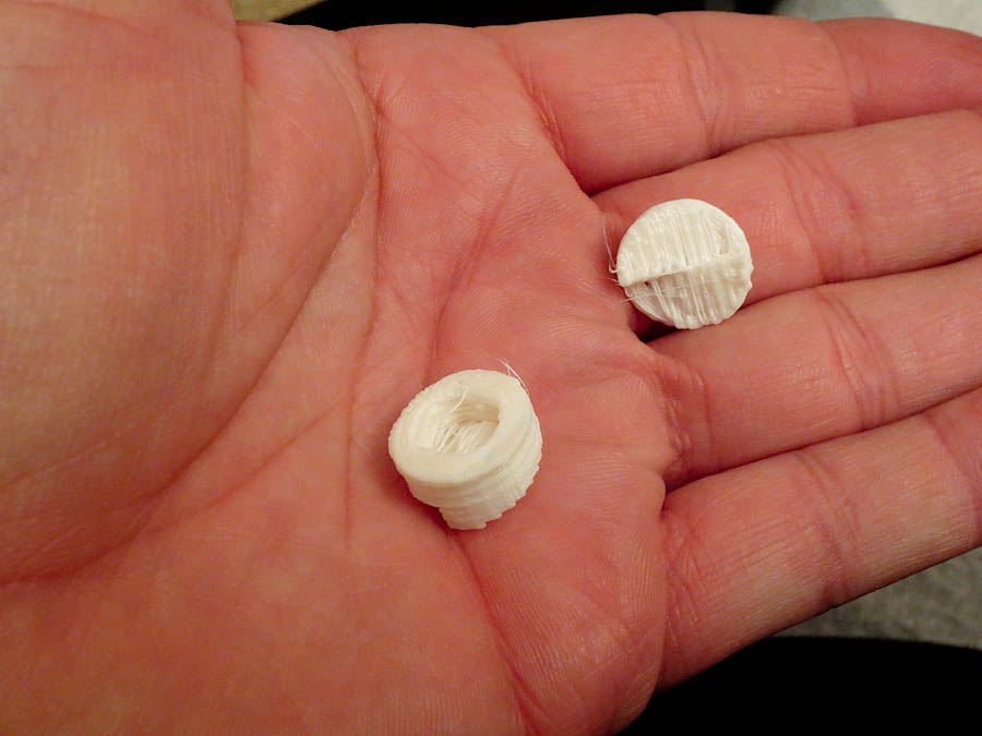
The above photo shows the  final parts ready to be removed, cleaned up and snapped in the cable chain.  You can see the first few strands of the upper crosspiece drooping down. These are easily removed with an sharp hobby knife.  I hope this helps you to better comprehend how parts are built on a 3D printer. There are a number of different printing technologies out there but all of them use the same basic principle,  depositing a single layer on top of another layer to build a solid object.   Perhaps I’ll do another post comparing the different types of 3D printers out there in the near future. 

As always, if you have any questions please ask.

Large 3D Printer heated bed (build platform) issues

Nichrome wire heated bed for 3d printer-2

Building a larger sized 3D Printer comes with the challenge of making an affordable heated build platform. The build platform must be as flat as possible. The build platform for my 3d printer also needs to be heated in order for the plastic to stick.   My printer is a Fused Deposition Modeling (FDM) type machine and different plastic filaments require differing bed temperatures(110C for ABS, 60C for PLA, etc). The  build platform on my 3D printer, often called a heated bed, is 19 in x 13.5 in x 0.250 in. This is considerably larger then the build platforms on the many hobby scale printers being built such as reprap (7.8 in x 7.8in) and makerbots replicator (11.2 in x 6.0 in).   Heating such a large areas is difficult.    My heated bed V1.0, shown in my previous post showing the first 3d printed parts,  was 0.065″ thick 7075 aluminum with 3/4″ angle aluminum edge supports around the perimeter.  Version 1.0 did not do well when heated to 110C for the test print.  The thin aluminum warped very badly after the first printing leading me to design a V2.0 heated bed from 0.250″ thick aluminum plate.  I did not have a large enough piece of aluminum on hand so I asked my project loving friends for help.  My most awesome bud Joe came through with a large piece of 0.250″ aluminum plate I could use.  I machined it to size and then got to work on making a heater on the bottom side.

Nichrome wire heated bed for 3d printer-3

The heater is built onto the bottom of the build platform using nichrome wire.  I used 0.001″ thick polyimide (aka Kapton tape) to cover the bottom side of the aluminum plate completely.  Polyimide film has excellent properties and can handle continuous temperatures of up to 260C.  I had used a 300W Watlow flexible heater on the heated bed v1.0  and I felt that 300W was a good target power for my heater design.  I also hoped to use 120V line voltage rather then have a huge 12V DC power supply (300W at 120V is 2.5A, at 12V it is 25A).  I did the necessary calculations to determine that I needed roughly 30 ft of nichrome wire for the heated bed. I then carefully laid the wire out on the platform using small pieces of kapton tape (seen in the above photo) to hold each wire down in place.  Finally I covered the entire plate with 2″ wide Kapton tape to insulate and hold the wires in place.

 inslating a heated bed on 3D printer    silicone adhesive for nicrome wire heated bed 3d printer


To provide some insulation and limit heat loss to the ambient environment I used high temperature silicone RTV (purchased at my local hardware store) to seal down the nichrome heater and to adhere a sheet of ceramic insulation board.  I had the ceramic sheet left from an earlier project.   If you follow in my footsteps, be sure to do the spreading of the thin layer of rtv over the heater outside or with a fan in a well ventilated space.  All of that RTV spread out over a large surface area can burn your eyes and lungs without proper care and safety gear. I wore a respirator and worked outside.   Then I used some solid plastic boards and old laptops to squish the ceramic board, Silicone rtv and nichrome wire onto the back side of the build platform the 3d printer.  I let the RTV cure for 24 hours before mounting it on the printer.  The bed is temporarily mounted with steel clamps for testing purposes.

Control hardware for 3d printer heated bed        3d printer heated bed power control-7305

The heated nichrome wire runs a little hot.  I chose to use a Variac to control the voltage and limit the upper temperature of the wire.  I’m considering peeling the entire heater off the bed and using a very thin layer of rtv to seal it to the aluminum plate.  I’m concerned about the wire getting hot enough to degrade the polyimide film and short circuit the 120V to the heater bed.  To alleviate any risk, I’ve combined a GFCI plug with a 3A fuse on the heater  In the above photo you can see the blue variac as well as the black SSR control box I am using to switch the heater on and off via the RAMPS 1.4 hardwares 12v control pin.  This heated bed works well, but still has some inherent stress from being rolled.  I made a jig to test flatness of the bed and measure out about 0.025″ out in the x direction, and 0.010″ in the y direction across the build platform.  I plan to order some cast MIC-6 Aluminum plate for V3.0 eventually.

alignment jig for heated bed on 3d printer

I created the alignment jig above to help align and level the heated bed on the printer.  The bed sits on 4 adjustable pads off of the the y axis carriage (seen by clicking here for a photo).   This allows it to be adjusted so it is perfectly flat relative to the print head.  Using a dial indicator goes a long way to simplify the adjustment process. I considered using a digital angle finder but as I don’t have one on hand this was the best way to go.  I was able to center any out of flatness by adjustment of the four mounting pads.

3d printed cable guide chain-7251    3d printed cable guide chain-7248

It wouldn’t be a post about 3d printing without showing some printed parts.  This is a link of cable chain.  I’m using this part as the test piece for dialing in all of the parameters to get the best possible print quality.  I felt this was a good part as it has fine detail, lots of overhang, and a 15mm span across the top.  More on the function of this part in the next post, but it will be used on the printer to keep wires from crimping on the x axis.  

First parts printed on my 3D Printer

3d printed test parts

The very first parts printed on the 3d printer I have designed and built.  Nothing glorious. Frankly I was expecting nothing to happen when I clicked print.  I had not finished all of the final alignment adjustments needed to the build platform and frame. This print happened while I was testing the build platform heater for the first time. To see how the software worked,  I loaded a small stl part file (the two pieces are a hub for a whirlyprop kids toy) mostly to see how the software processed the file. After playing with the code and making adjustments to some settings,  I said to myself, “Let’s see what happens.”, clicked print and voila parts were made.

Zac 3d printer- First printed parts-2413   FDM 3d printer test print

 The above pictures show I still have  a lot of work to do on optimizing parameters in the software code for my unique printer design.  It did surprisingly well spanning the overhang with only a few loose rows of filament being out of place due to droop.    The acrylic adhesive on the blue masking tape smelled something terrible after heating. This is due to some thermal degradation of the adhesive.  I was happy it peeled off the build platform cleanly.  The blue tape is used to help the abs stick to the build surface as it is extruded in the first layer.  I had ordered some 2″ wide polyimide tape but was waiting for it to arrive when I printed these very first parts on the printer.

parts in hand from 3d printer

These parts are the very first things the 3d printer I designed and built ever printed.   I was pretty excited when I saw my design in action printing.  The printer is not “done” by any means. There has been a heated bed V2.0 built and installed already.  The #1 issue I have found with designing and building a 3d printer that is much larger than the majority of cupecake, makerbot, reprap style printers people typically build is flatness of the build platform.  More on this in my next post.

A quick easy way to make an XL series timing belt mount

XL timing belt mount

Timing belts are useful for all sorts of synchronous motion.  They can be used to connect a rotary encoder to a lathe spindle or to provide linear positioning on a 3D printer.  They have little stretch or flex and can accurately transmit rotational motion.   One of the challenges with using timing belts is mounting them in your projects.  This is especially true when you want to use timing belts to convert rotational motion of a computer controlled stepper motor into positionally accurate linear motion on a project like my 3D printer build.  Here’s a fast and easy way to make yourself a timing belt clamp and mount for your project.  The clamp shown in this post will function as the y axis mount on my DIY 3D printer (photo installed at the end).

how to make a timing belt clamp using hot glue-1645

Any craftsman, maker, car guy, or project loving person knows about and owns a hot melt glue gun. They are good for many things,  in this project the hot melt gun is going to provide the plastic uses to pattern our timing belt interlock features on a substrate.

how to make a timing belt clamp using hot glue-1648    L series timing belt clamp

Wear gloves when playing with hot things!

First you need to make a mounting block for use as a substrate from your material of choice.  Aluminum in this case.  I machined the part to fit onto my 3D printer’s y-axis structural cross member.  I cut a small scrap of XL series timing belt to fit the groove. This is why it is always good to hold onto things like a scrap bit of timing belt.  It may be hard to see in the picture above but I drilled a series of 6 shallow holes into the timing belt slot to allow the molten hot glue to seep in and form mechanical interlocks.  It’s best not to rely on the adhesive strength of the hot glue, mechanical interlocking features for the polymer to mold into provide good shear resistance.

Pre-heat the substrate.  You could use a project toaster oven,  heat gun, 500w lamp, etc.  I used the woodstove.  If you try this with a cold substrate the hot glue will cool too quickly to mold to the features of the timing belt. You want the substrate warm so it does not pull heat out of the molten polymer before we can mold it to the timing belt.

XL series timing belt mount using hot glue - 7

Quickly take your preheated substrate from your heat source, put it on a nonflamable surface (leather glove in this case) and fill both sides with hot glue quickly.  Use a bit more then you think you need, it will seep out the ends if there is too much in the slot.

XL series timing belt mount using hot glue4

Then clamp down the timing belt into the molten plastic with the screw. I used a long screw to provide alignment and a nut to make clamping  easier and faster.  It is also acceptable to just squish it down with your fingers.   Put the hot assembly into cold water to quickly cool the hot melted plastic before it can seep out of the cavity.

XL series timing belt mount using hot glue

Let it cool completely before disassemble.  I’ve never had any issue with the hot glue sticking to the timing belt enough to be a problem.  Usually it is possible to remove the Timing Belt used to mold the plastic with fingers. If it is a bit stubborn in coming free use a small pair of pliers to get a grip on the bit of timing belt and slowly pull it up and away.

XL timing belt mount

When disassembled, trim up any of the plastic that seeped out with a sharp exacto knife or chisel.   As you can see you get a perfectly molded Timing Belt clamp that can be used for your project.

XL series timing belt mount

Here’s the finish timing belt in place on the 3D printer project.  The stepper motors have 10 tooth pulleys on them to drive the XL series timing belts allowing the y axis to move with positional accuracy.  More on the 3d printer progress as I have time to write.  It is nearly operational!