As I near completion on my 3D printer build, I found myself needing a way to drive stepper motors to quickly test axis motion (watch the video at the end of this post). To that end I threw together this low cost stepper motor drive. It is based on a Pololu A4988 stepper motor driver being run by a 555 timer set up as an oscillator. I wanted something cheap that I could quickly throw together to test the motion on the axis as well as keep handy for future stepper motor projects. I spent a little more time on this project then it warranted but now I have a great little stepper motor drive for testing future projects.
The circuit diagram above shows the basic schematics for the stepper motor drive. Sorry about the chicken scratches on paper version, but all the info is there if you want to make one of these for yourself. As always if you have any questions shoot me an email at: zac AT projectsbyzac.com The 555 timer is run as an astabile oscillator to generate the step pulses to drive the Pololu A4988 stepper driver (A4988 data sheet is here) & (Pololu A4988 datasheet is here) . If you’ve read my previous post on building a cnc machine control box based on Pololu 4988’s you know I love these little stepper drive boards. They are similar to stepstiks (drop in pin for pin replacements in fact) which will eventually run the 3d printer on the RAMPS electronics which just arrived. There are newer drop in higher performance Pololu models available now but I had a A4988 green boards on hand. To allow for variable motor speed control I used a 10 turn 10K potentiometer inline in the 555 circuit. This allows the drive speed to be varied by turning the knob. The pot I used has a digital read out. When I find a speed that works well to test a particular motor/axis drive, I can easily set it in the same speed in the future. Thanks to Adam Perkins for these 10 turn pots. I traded him some parts a few years back for a few of these 10 turn pots with read outs. This is the first project on which I have used one of them. He has a very useful webpage with great info on electronics and is my electonic project mentor from my UNH Days.
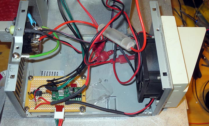
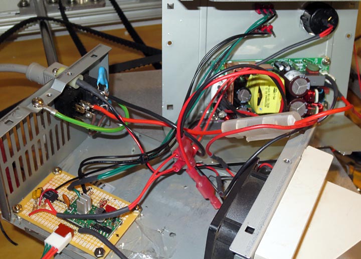
 The circuit is soldered up on a small board from Radio shack. I’ve housed the entire project in an old PC power supply case. I love using PC power supply cases for projects and always have a couple on hand in my parts inventory. They have good cross flow cooling, built in fan, switch and power cords making them the perfect project enclosure. The pololu A4988 can handle up to 2.0 A with a heat sink and air flow for cooling which the power supply case fan supplies. To power this project I initially used a spare 12v 2.0A wall wart installed. The supply was noisy and it was affecting the stepper motor drive output. Additionally when it was driving the motors I could hear the cooling fan speed decrease, so it wasn’t up to the current draw needs of the motors being tested. I changed over to an Astec LPS50-M Series 60 Watts power supply I had on my parts shelf. This supply could easily handle the motor load and would provide a clean 15 volts, the supply used was an Astec LPS54-M (datasheet for the LPS54M powersupply is here).
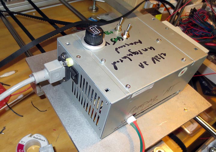
The above photo shows the finished product. I used my CNC machine to mill out the top of the case for the pot with the readout and drill holes for mounting the power supply and the 2 toggle switches. One switch controls the direction of the motor (dir pin #14 on the pololu) and the other interrupts the signal between the 555 oscillator and the step pin (pn #13 on the pololu) allowing to start and stop the stepper motor without powering down the controller.
The above video shows the driver being used to test the Z axis on the 3D printer. I have the current control way down so when raising the axis the motors struggle a bit (the sound you hear changes from the smooth driving on the way down). I thought some of you might enjoy the video clip. There will be more videos as the printer is further tested now that I made a youtube account to host them.


Are you driving two steppers at once with this box? It looks like you are in the video you posted.
Yes, I made a board up that splits the stepper signal between two motors. The RAMPs v1.4 electronics has this feature built into the Arduino shield and I wanted to test out the axis motion. It seems to work well driving two steppers simultaneously.
Dear Zac
I am taking your suggestion assembly.
In your diagram where you explain how to connect with the plate 555
a4988 stepper motor drive, I have a doubt about the toggle switch.
I do not understand where it is being connected.
In the drawing are: earth, 10K resistor, the switch, yet another 10K resistor and
Then vcc. Can not understand it. If you can also help me on
if pins 4 and 5 are connected together to ground.
Thank you for your attention.
I put the 10k resistors to limit current on the off chance something goes wrong. I had an issue with it jumping about when I left one end of the toggle floating on the Direction pin, so I tied it to +5V and 0V. this is likely not the best circuit design ever, It was something I threw together quickly to test my 3D printer while I was designing/building it and then had forum friends ask about how I made the stand alone test driver so I shared.
On the Pololu, Pin 4 (3.3V) is not Connected to Pin 5 (ground). I see why you are confused by my chicken scratches on paper. I’m not sure but I think that might be some marking from the back side of the paper that came through. When I have time I’ll try to edit the image to fix that. Sorry about the confusion.
Hello Zac, thanks for the response.
My circuit is almost finalized. I’m looking forward to run a motor.
To make it clearer for me, the DIR pin Pololu being connected in the DC switch assembly. Is it? Sorry insist – do not know much about electronics.
Thank you.
yes it’s connected to the center of a 2 way switch. This way it can either be tied to ground or to 5V (high) allowing you to change direction the motor is running. There’s no debounce on the pololu so it may act a lil funny when you switch it at first but for a test mechanism this works well enough I’ve found. I have used this stepper driver to test a bunch of small steppers now without any problems.
We have this website called EasyEDA, we use it to make pcb schematics. You should try it. you can purchase components and pcb’s from JLCpcb. Probably a lot safer for those components.