About a year ago I started building a 3D printer based on the RepRap 3D printer community. Progress essentially stopped with the arrival of spring (aka adventure season), but it is once again project season (aka winter). My 3D printer build is approaching the testing phase for axis motion, print head extrusion quality and laying down my first builds. This post will show the progress and provide some thoughts on the design of my 3D printer.
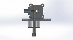
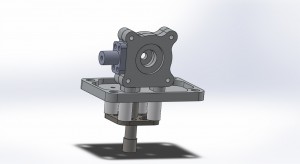
Last winter I had worked out a rough design for my own plastistruder 3D print head, I made a first go at my own design but felt I could do a better job. I had set the x axis such that it would mount a plate with 1.5″ on center bolts allowing me to experiment with different print head designs by having them be modular and easily swapped out. The above renderings show my current design for a 3mm filament plastic extruder. Based off the MK6 extruder from makerbot (that they apparently no longer support or sell), it was designed to use the same nozzles and 40W 12v cartridge heater.
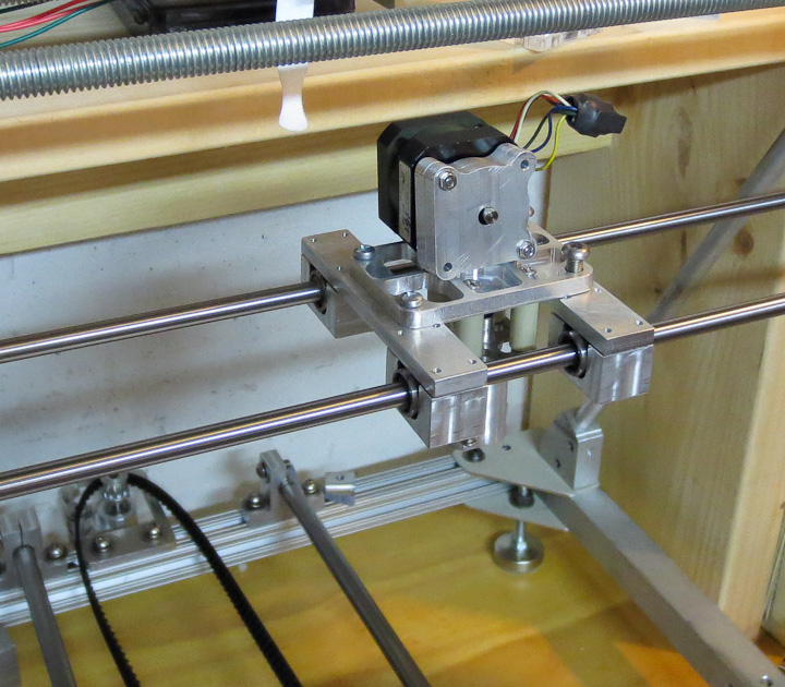
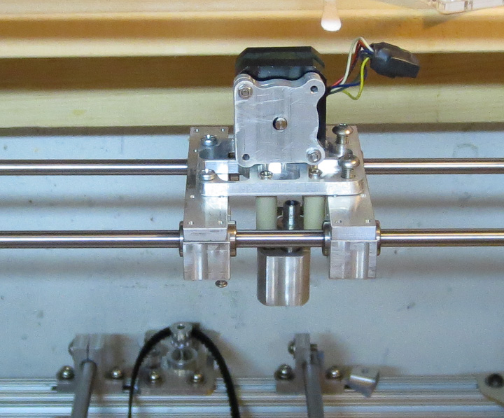
Above you can see I’ve finished the x axis mounts. They are functional but had any weight reduction done to them yet. The mounting plate and heat break/hot end side are done. I plant to machine down a pc heat sink to mount to the body of the extruder opposite the NEMA 17 stepper that will drive the filament into the hot end and out the extrusion nozzle. I found online a great little 1.75mm extruder head that I purchased here at a company called QU-BD and have ordered one since they are so cheap. I will test out both of them and compare results in a future post.
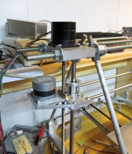
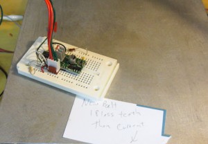
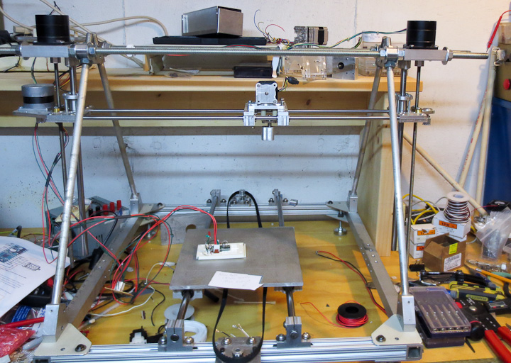
The Z axis design in my printer is basically two steppers driving threaded shafts from the same stepper pulse signal. This seems to work well and has been done in other reprap 3d printer designs. I am doing basic motion testing of the axis with a 555 timer as a pulse generator to drive a pololu A4988 stepper driver board. These are great little boards for running steppers and I have used them in other projects like my cnc control box. It’s a crude set up but does not require having a computer dedicated to this thing yet.
What’s left to get this thing running? I need to order some new LX series timing belts the correct size for both the y and x axis. Build a y axis chassis that is lighter then the solid aluminum test plate you see in the above pictures and then mount my larger heated build surface. Then it will be another round of electronics headaches. Hopefully this time the supplier for my reprap electronics board doesn’t send me junk. See my earlier post for my problems with the first Gen 6 electronics I ordered. Then it will finally be time for testing and printing parts. I already have a list of things to print out a mile long. Several friends want me to print them out the standard rep rap parts. I plan to help them out. Everyone should have their own 3d printer at home.

One thought on “DIY 3D Printer Progress”