Tag Archives: linkedin

Assembly and evaluation of the QU-BD MBE 1.75mm Filament Extruder for 3D printers

3D printer head 1.75mm filament extruder

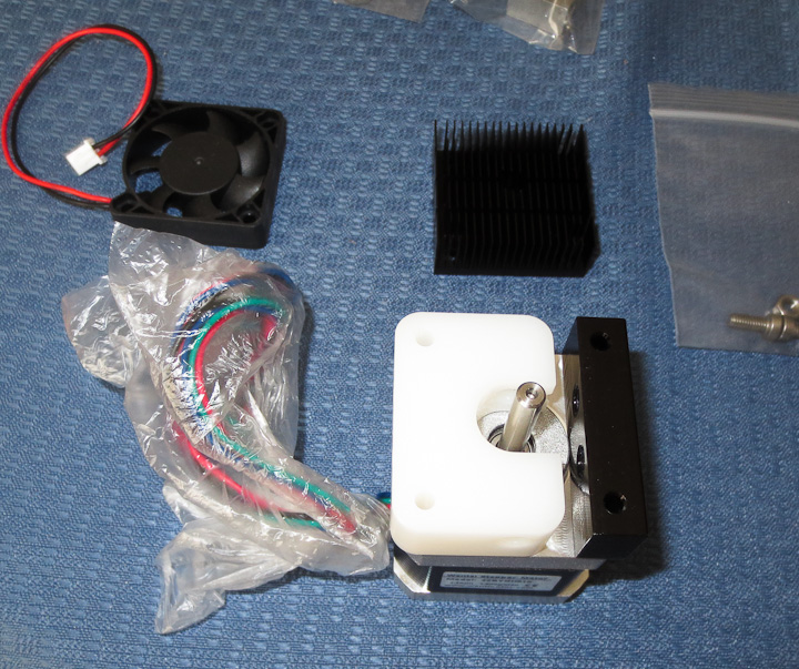
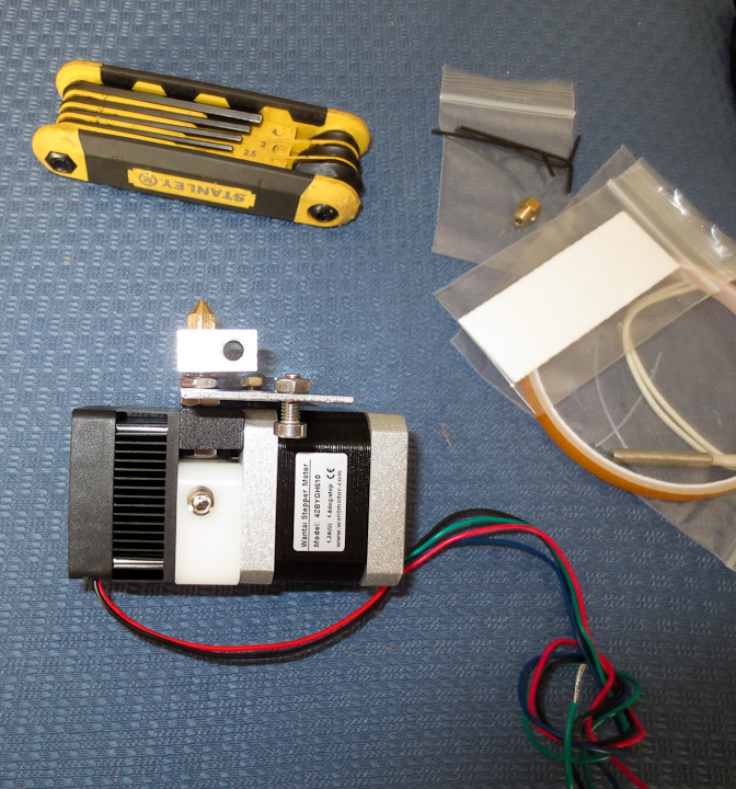
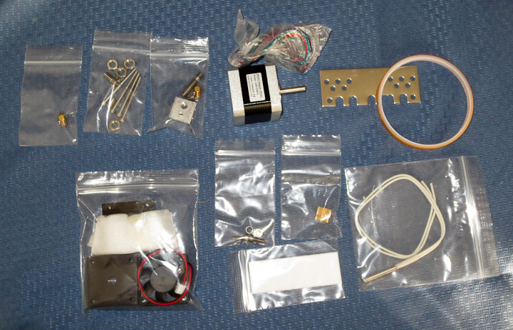
If you haven’t seen my earlier posts, I’m building a 3D printer, roughly modeled after the RepRap Prusa and RepRap Mendel designs but considerably larger.   In an earlier post I shared my own 3mm filament stepstruder plastic extruding 3D print head design and photos showing progress on its development.   While searching the interweb for nozzles to purchase, I came across the QU-BD website with 3D printer supplies.  Given the low cost (starting at $34, $63 all decked out with bullet heater and stepper motor) of this 3d printer extruder, one was ordered on the spot.  It was as received as you see in the above photo.  All of the parts were nicely segregated into plastic bags.

3D printer head by QU-BD

The first step was to tear into the packages and examine the parts.  The design is simple and well thought out.  It uses a combination of off the shelf components and custom machined pieces.  I really like the modified heat sink and small fan.  These two parts will also  be used on the 3mm filament print head of my own design as well.

3d Printer head assembly MBE v9

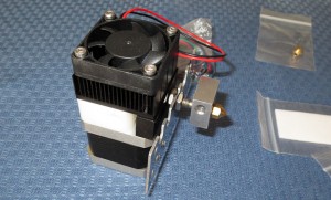
Assembly instructions are available on the QU-BD website here  or available on my site saved as a pdf here.  The above shows the body of the 1.75mm filament plastic stepstruder  on the NEMA 17 stepper motor that came with the kit.  Here is the data sheet for the Wantai 42BYGH610 stepper motor included in the QU-BD MBE V9 3d printer extruder kit.

3d printer head stepper extruder   d printer head stepper extruder

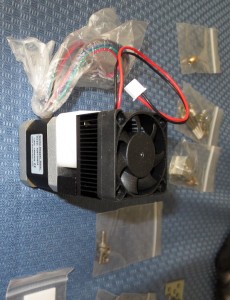
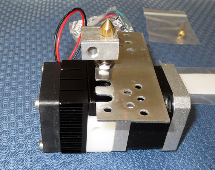
The kit assembled relatively easily.  All of the parts were well machined with the exception of the aluminum rectangular heater block.  The M6 threading was drilled and tapped at a slight angle (~5 degrees).  The result was that the nozzle did not sit flush against the block when tightened in place.  In the photo below you can see the misaligned angle of the heater block in relation to the body of the stepper motor and extruder.

3D printer head by QU-BD

I felt this minor issue was not worth the hassle of calling and complaining to QU-BD.  In fact given the price of the kit, and the DIY nature of product, issues like this are to be expected.  Some quick machining on the lathe squared the faces up to the M6 threaded through hole correcting the problem.

3D printer head by QU-BDA

The overall design of this 1.75mm filament stepper based extruder 3d print head is well thought out. The parts are all well made with the exception of the heater block.  The only piece that I felt was not useful in this kit was the included mounting plate.  This part will not  be used in my printer build but I suppose it is bolt in for some of the popular DIY 3D printer projects available in kit form.

3D printer head by QU-BD

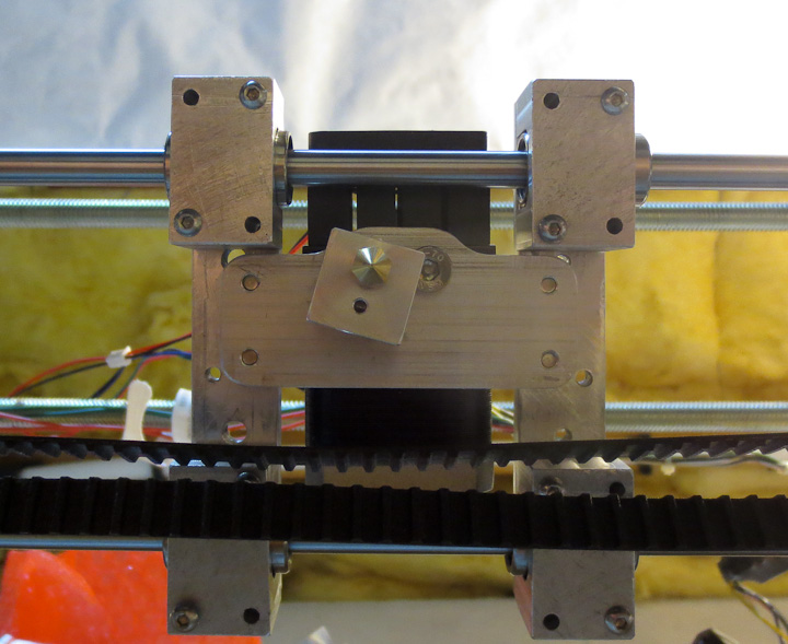
In the above photo you can see my mounting plate. Because of the much shorter hot end/nozzle portion on this 1.75mm filament plastic stepstruder I needed to drop the entire head as close as possible to the linear shafts that make up the x axis on my 3d printer build.  I machined a 0.150″ drop into the mounting plate. This gets the nozzle down almost  well below the timing belt and linear bearing mounts.

3D printer head by QU-BD

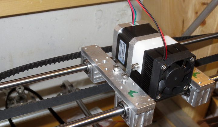
Here is the QU-BD MBE v9 Extruder in place installed on my 3d printer.  It is small, looks good, and fits well with the rest of the machine.  As of now my printer has mounts for 2 different print heads.  Eventually I’ll settle on one or the other and machine new bearing supports (the aluminum rectangles with the green M’s on them) to reduce mass as much as possible.  Less mass means less inertia resulting in faster print head movement.  The plan is to redo the bearing mounts as well when it is fully operational.  They will be produced by printing them out in ABS, thus having the machine produce upgrade parts for itself.


How to CNC machine a part from start to finish

Several readers have asked me for a post explaining the entire part creation process starting with a part concept, going through fabrication and ending with the part in use.   I use a ZAY7045 (RF45 clone)   Milling machine that I converted to CNC  to make parts for my projects.  In this post I will be sharing the details on the CAD design of parts, CNC coding, and fabrication process.   I will be using a two different pieces ( a headlight mounting bracket  and a speedometer mounting bracket) I made recently for my Honda CX500 Cafe Racer build to illustrate and outline the basic process of CNC fabrication of custom components.   I will keep the details simple such that everyone can understand how the CNC fabrication process works.
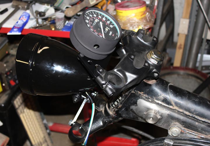
Speedometer mounting on a CX500 Cafe Racer

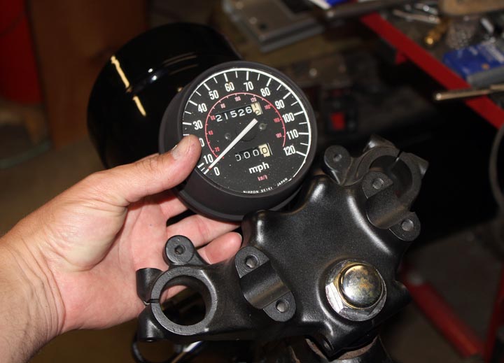
All parts start with a need,  in the photo above,  I need a bracket to locate and mount a single gauge to the upper triple clamp on my Cafe Racer Motorcycle Project.   I start by holding the speedometer gauge in place and taking some measurements.  It’s critical to carefully measure details like mounting bolt hole spacing.   As a rule of thumb I measure the smaller and larger dimension and take the midpoint between those numbers.    Here’s a Zac Shop Tip:  if you measure and calculate 138.43 mm,  it is very likely the actual value is the next nearest whole or half number,  ie. 138.5mm. After writing down the measured values on a small notepad, I next go to the computer to draw up the part.
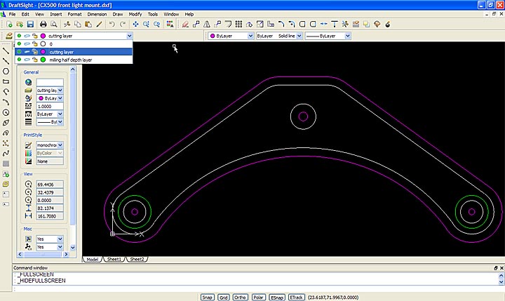
Cad drawing of cnc machined part with different layers for different operations

After careful measurement, it is time to draw up your part in a CAD software package.  I’m quite fond of Dassault Systems, Draftsight software for generating simple DXF and DWG drawing files.  I am familiar and proficient with Solidworks, a 3d design software package which makes using the free Draftsight .dwg/.dxf CAD software an easy experience.  The above screen shot shows my version 2.0 headlight mounting bracket as drawn in draftsight.  You can see the part layer in white, the cutting layer in magenta, and the milling layer in green.  I manually set cutter offset in my drawings (a topic for another more technical post).  Each layer will have a different code generation step in the next part of the process.  Separating them out here makes life easier later on when generating the G-code for the CNC Milling Machine.
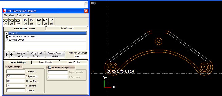
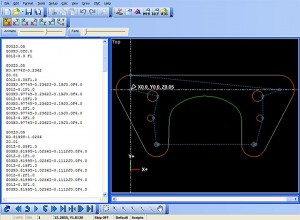
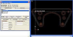
The CNC code generation software I use is not great, but I can not afford very expensive enterprise level software for this stage and thus I make do with what I have available.  I use this software to put the basic building blocks of the code in place.  I then rearrange, and edit the Gcode (CNC Machining programming language) into a form that is more usable and efficient.  The above photo shows a screen shot of the step in the process where I can set individual layer settings for the cutter.  You may recall I explained the need to generate separate layers earlier in the post and this is the purpose.  If you do not separate operations into layers you end up having to do a lot of tedious manual editing of your CNC Gcode program.
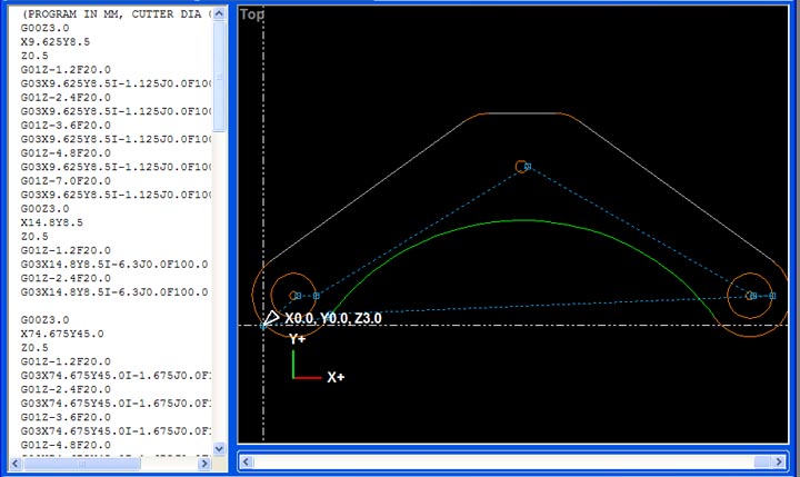
CNC Gcode generation

After chaining the layers together, so that the machine can generate code that does an entire loop in one go vs each individual drawing item  one at a time,  the software generates a basic G-code program.  I then carefully reorganize, and edit the code to make the program safe, do what I want, and in most cases more efficient.  The software tends to break things down such that the machine spends a lot of time traveling between points of entry into the material.  I reorganize the code snippets to minimize this which in turns shortens the machining time considerably.
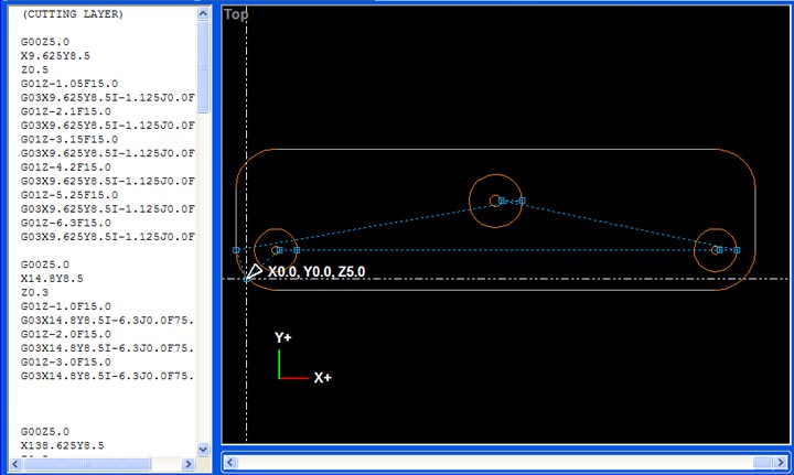
The above photo, is the Gcode generation for the v1.0 headlight mounting bracket.  I made this first part as a fast test of the mounting location and strength of the 1/4″ thick 6061 aluminum plate I would be making this part from.  I will use this part in the next couple pictures vs the V2.0 headlight mounting bracket we’ve seen in the post so far.  I did not plan to put this post together ahead of time and missed some pics in the process with the v2.0 mount.   Rather then wait till I build the next part, I wanted to get this up to help my readers understand the process as soon as possible.
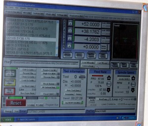
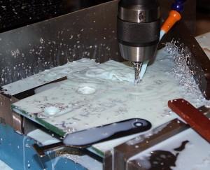
CNC machine software controlling the milling of a part   

Above you see a screen shot of the CNC machine control software running the machining process.  After lots of careful checking and setting a zero point on a larger piece of metal “stock” clamped into the machine I start the program and the machine does the rest.   This is really fantastic when you are making 4 of one part as after the first time the code has run through and is validated I will start the program and leave to do other tasks in the shop.  My CNC machine is not 100% self sufficient yet, so I periodically monitor it when it runs.  The number one problem with my current set up is coolant spraying everywhere making a real mess.  I plan to place the machine in a full enclosure at some future time.
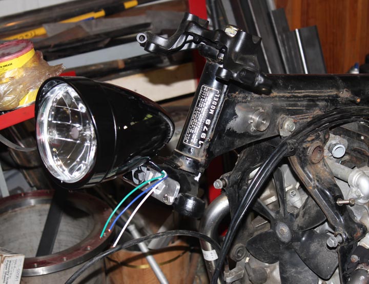
CX500 cafe racer headlight mount Ver 1.0

The above photo shows the cafe racer headlight mount version 1.0 in place on the bike.   While this was a functional part, I learned I needed three changes for version 2.0.  The first change is that version 2.0  needed to be less ugly.  Aesthetics are important on some projects, and my Cafe Racer is to  be a thing of beauty.   Secondly I learned that I wanted to raise the headlight another inch or so in version 2.0.  Third I needed a slot to keep the headlamp from rotating, especially important to prevent it rotating with riding vibrations over time.
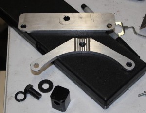
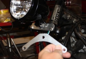
    CX500 Cafe Racer custom CNC fabrication

Above you can see the version 1.0 and version 2.0 parts together.  Clearly version 2.0 is superior in every way.
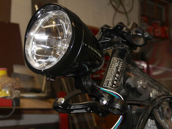
Custom CNC cafe racer parts built to orderAbove is the finished and painted bracket with the headlight mounted on the bike.   I am quite happy with the way it came out in the end.
     CX 500 cafe racer CNC fabrication

Similar to the headlight mounting bracket, I generated the code for the gauge mounting bracket for the speedometer.  This program required considerably more reorganization of the code to make run efficiently.  I use a simulation to determine the program run time.  The “as generated”  Gcode had a run time of almost 45 minutes.  I managed to get that down to 28 minutes by manually editing and reorganizing the G-code in the program.
CX500 Cafe Racer parts made to order   

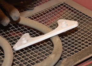
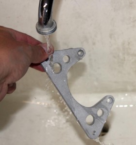
Now for a bit on post CNC machine processing of parts.   I start by deburring all of the edges with either a deburring tool, a fine file, or sandpaper.   The machining process often leaves razor sharp burrs on the edges where it cuts the metal. The  parts used as examples in this post were primarily deburred with sandpaper.  I then wash them with warm soapy water to remove any cutting oils and coolant left on the part.  A quick trip to the sandblasting cabinet and they are left with a fine surface finish ready for paint.  Another trip to the shop sink to wash off any residue sand from the blast cabinet and they are ready for painting.

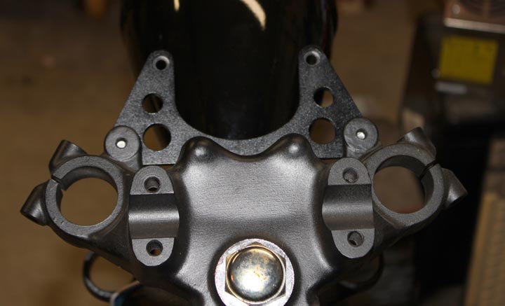
I often paint small parts like these brackets hanging from bits of bent copper wire through a bolt hole.    Several light coats of a quality paint results in a hard durable finish.  A hairdrier (buy one especially for this purpose, do not “borrow” your significant others for painting car parts) can be used to help flash dry the paint between coats, or in the winter time cure the paint quickly in colder temperatures.
Cafe racer guage mount speedometer

Here’s the finished CNC machined bracket on the bike.
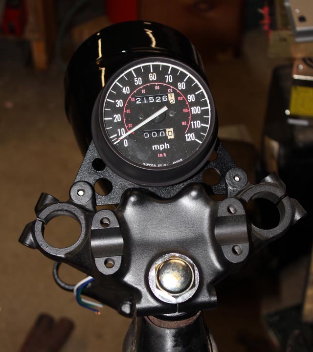
Cafe Racer Speedometer  CX500

    I am very happy with the way these parts came out and the overall look on the bike as this project progresses.  If you want more information on these parts (drawings, etc)  or would like me to make one of these parts for your CX500 motorcycle project,  leave a comment on this post or email me at zac at projectsbyzac.com.  I hope this helps my readers understand the process of how to make parts with a CNC machine.  When I finish my 3d printer project I will do a similar post on 3d printing parts from start to finish.

I’ve gotten a number of requests for the drawings I used to make these parts. Here are the DXF files I used to mill each of these brackets, this was before I had real cam software so they are ofset by 0.125 for G-Code generation via very primitive software.   I had to convert the DXF to PDFs to share them with you in wordpress.  It claims DXF is a security risk.  You can convert back or open them in your cad software and everything should still be ok.  CX500 front light mount   &    cx500 guage mount
antibacklash ballscrew upgrade on RF45 ZAY7045 Milling machine – Part 1

Antibacklash ballscrew upgrade for RF45 ZAY7045 milling machine

I converted my lathemaster ZAY7045 milling machine (a RF45 clone) to 3 axis CNC about 3-4 years ago with whatever parts and materials I had on hand as a proof of concept experiment.  The CNC conversion was one of the best things I have ever done.  I instantly fell in love with CNC machining.  At the time, I made the decision to run with the original very poor ACME threaded leadscrews with their 0.100″ pitch, AKA 10 turns per inch.  My original conversion could hardly be called more than a down and dirty hack but it did work.  Several problems with my original approach became apparent.  First and foremost  among my cnc machine woes was the ridiculous backlash on the factory parts, especially on the x axis leadscrew.   I programmed and tuned anti-backlash algorithms in my control software that are quite amazing, but they only compensate for the backlash rather then remove it.  With the extensive use the CNC mill gets  the backlash had been growing worse steadily. When the backlash reached 0.047″ I decided it was time to replace the x axis ACME threaded leadscrew with a nice anti-backlash ballscrew setup.


A 20mm diameter ballscrew and associated ballnut were the largest that would fit under the saddle.  As is often the way with tools, bigger is better when it comes to a ballscrew and it’s load handling ability.   In this case it had to move a few hundred pounds of table, motor, vice, stock, cutting fluid, etc.  I initially wanted to stuff a 25mm diameter ballscrew under the table, but after disassembly, careful measurement showed that it would not be physically possible to use 25mm diameter ballscrews.  The new 20mm ballscrew will have a metric thread pitch of 5mm, roughly traveling twice the distance per revolution as it did with the original acme leadscrew.  This is not a problem as the CNC software I use to drive my CNC mill can easily compensate for the change in the leadscrew thread pitch.  The calculations to determine the new movement per step are basic and straightforward.


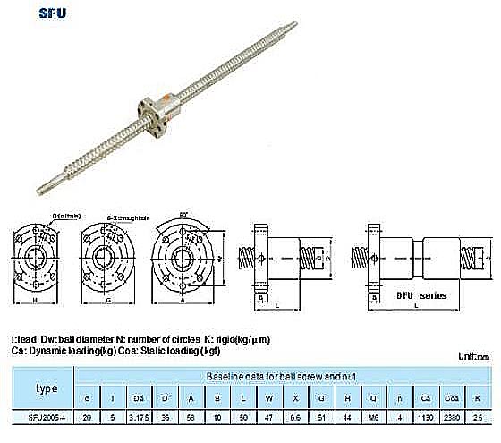
I don’t intend to wax poetic on the variety, quality, and types of ballscrews available. Plenty of companies offer excellent reviews of Ballscrew engineering calculations and selection criteria.  I chose to use a 20mm ballscrew with a 5mm pitch (Part #: SFU2005-C7 ) of 975  mm in length, available from kellinginc cnc. See the dimensions and specs below.

detailed specs for the SFU2005 ballscrew2005-c7-975mm ballscrew end machining drawings

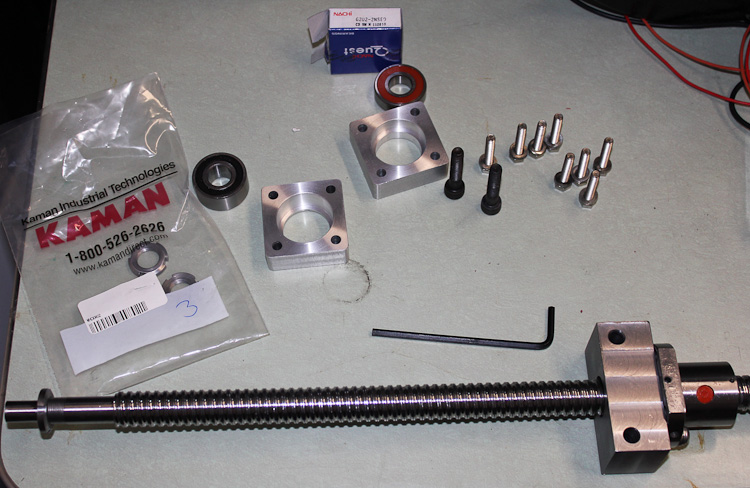
Dealing with Kelling Inc. is problematic at best. I have made four separate purchases from them, and twice I have had problems.  One time they sent me the wrong part and then tried to make me use what they sent instead of what I ordered in spite of it not working for my application.  Finally though,  Kelling Inc. resolved that particular issue by sending me the part I ordered but it was a hassle to get them to do so.  With the ballscrew, my issue was that unlike other vendors they do not including the 15mm x 1.0mm nut that threads onto the ballscrew to clamp it against a 5202 double angular contact bearing.  Having used higher end ballscrews for industrial repairs and machine designs in the past experience shows that other vendors include this nut (a sub 1$ part) with their ballscrews.  Kelling inc’s answer when I called to discuss this issue was that the nut is not included, nor available for sale individually, but I could buy their fixed end bearing mount BK15-C7 (Fixed End) for  $82.95 and then get the 15mm x 1.0 mm pitch bearing retaining nut I needed. I was not about to spend $83 for a $0.87 part.   With no solution offered by Kelling Inc. I set about finding the rare and elusive 15mm bearing retaining nut.  Scouring the net and my supplier database from the day job I found an industrial supply company that would sell me a few of the 15-1.0mm bearing retaining nuts manufactured by whittet higgins, part number KM-02. I ordered my 15mmx1.0 nut from the local KAMAN Industrial Technologies office down in Manchester as they would sell to me with no minimum order fee.
    

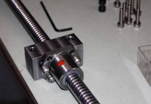
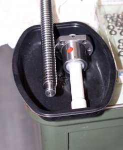
The ballnut came pre-installed on the SFU2005 ballscrew.  It was installed flipped 180 degrees from what was needed to work with my design for my CNC milling machine.  Removing a ballnut can be a lesson in frustration and hunting for hundreds of small ball bearings on the floor if you are not careful.  The short lesson on how to correctly remove a ballnut is as follows.  Machine a removal guide that fits over your machined ends and is the same outer diameter as the minor diameter of your ballscrews threading.  For my SFU2005-C7  ballscrew this minor diameter is 18mm.  I turned down a piece of sch 40 PVC pipe on my 100 year old lathe (yup it’s on the to be replaced tool list. As an  aside, it will go to an industrial museum as a donation when I do eventually replace it with the shiny new 14×40 Lathe I have already picked out for myself).  In the right hand pic above you can see that even though I used a ballnut removal tool, I still removed it over a tray.  This is just in case something goes wrong and all of the small steel balls fall out.  Better to be safe then sorry here, so use a tray.

   Upgrading to ballscrews on a RF45 ZAY7045 mill drill

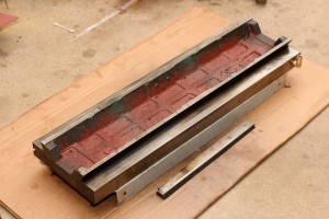
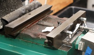
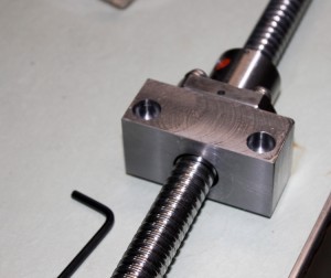
I designed the new ballnut mount  to fit the original 8mm mounting bolt holes on the saddle.  My ballnut mount design is such that there is no need to machine the ballnut. I did not want to risk contamination of the ballnuts internal raceway and bearing mechanism.   my design lowers the ballnut below the raised nut mounting boss on the saddle assembly. There is very little clearance in this set up, but it works well and does fit.   Here are technical drawings of my design: RF45 ZAY7045 mounting block for SFU2005-C7 ballscrew – sae units & in metric units   RF45 ZAY7045 mounting block for SFU2005-C7 ballscrew – metric units
As you can see in the upper left photo, I had to clip the corners of the ball nut mount.  This is not reflected in the above drawings, but you should machine the corners off the ballnut mount before disassembling your machine if you copy my design.  I did it by hand with a carbide burr and hand files.  Also note that I have not yet installed a zerk fitting into the ballnut. I hope I can find a tight M6-1.0 90 degree Zerk fitting that will fit and clear the table.  For now I plan to use grease on the ball nut.  In the future I will add a self oiling system to the CNC machine and will convert the ballnut over to oil lubrication at that time.  Oil lubrication is superior in that it tends to wash away contaminates from the ballnut rather then collect them as grease does.
That is all for part 1 of the ballscrew upgrade on my CNC milling machine. This post continues in part 2.

electrolytic rust removal restoration of an antique coal iron

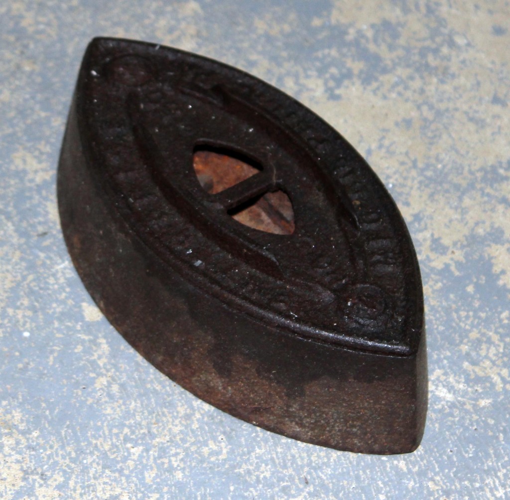
Enterprise MFG CO No 50  Antique Coal Iron

Last summer, I took my niece and nephew up to Clark’s Trading Post in Lincoln, NH to see the bears.  While there I went through Clark’s Florence Murray Museum of antique items and oddities.  There in the display cases I saw a few antique coal irons and realized I had one exactly like them, except rusty in the loft of the barn.  I made a mental note to restore mine so it looked as nice as the ones at Clark’s trading post.  This post shows how I restored my Enterprise MFG Co. No 50 Laundry Iron.
Above shows the iron as it was when I re-found it in the barn after my visit to Clark’s Trading Post.  The Coal Iron is marked ENTERPRISE MFG CO  PHILA PA  along the outer edge with NO 50 on the inside.   Enterprise Manufacturing Company was an iron works located at Dauphin St, American St, and Bodine St (SW corner) in Philadelphia, PA in the late 1800’s.  They manufactured a variety of household devices, including coffee grinders and laundry irons.  A bit of research shows my laundry iron  is missing it’s handle as you can see in this picture of the same iron from the Okawa Museum.  Even missing parts I felt  my rusty hunk of metal was destined for restoration. Perhaps I’ll make a replica handle for it someday.

electrolysis rust removal on antique iron     electrolysis rust removal supplies

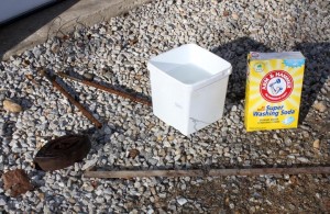
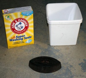
My rusty antique iron was the perfect candidate for rust removal by electrolysis.  The great thing about electrolytic rust removal is that it only removes the oxidized metal.  Unlike sandblasting or other mechanical means of rust removal, none of the good metal is removed during the rust cleaning process.  Having learned more about electorchemistry then I ever planned while working on my phd research, I figured this was a good time to put some of it to use.   All that is needed is a 12v source (another voltage is fine but keep it somewhat low to avoid excess heating and electrocution risks), a bucket,  some sacrificial electrode (steel rebar cutoffs work great), Arm and Hammer Washing Soda, some steel wire and a plastic bucket.

A few words on supplies.  Washing soda is what you want, it is also called sodium carbonate, Soda Ash or Na2CO3 .  It’s more or less benign and doesn’t break down into any harmful chemicals during the process.  Do not be tempted to substitute Borax, or baking soda.  Washing soda was somewhat difficult to find locally but Rocky’s Ace Hardware still sells it.   Another caution: do not use chrome plated or Stainless Steel anywhere in your set up.   The heavy metal ions are toxic making the waste solution very bad for you, me and the environment.   The waste solution with only washing soda and iron in it is harmless when you are done.

My rusty Iron is suspended by some steel wire twisted tightly about it to make a good electrical connection. I wire brushed the section where I attached the wire to allow for better electrical contact.  Mix the Washing Soda at about 1 heaping tablespoon per gallon.   Be sure to connect your 12V power source correctly.  The NEGATIVE (often labeled – or black) lead goes to the part you wish to restore.  The positive lead (often red or +)  goes to the sacrificial electrodes( aka steel rebar scraps).  If you reverse this you will dissolve and ruin your part instead of restore it.  It’s an important step so be careful not to reverse the polarity.


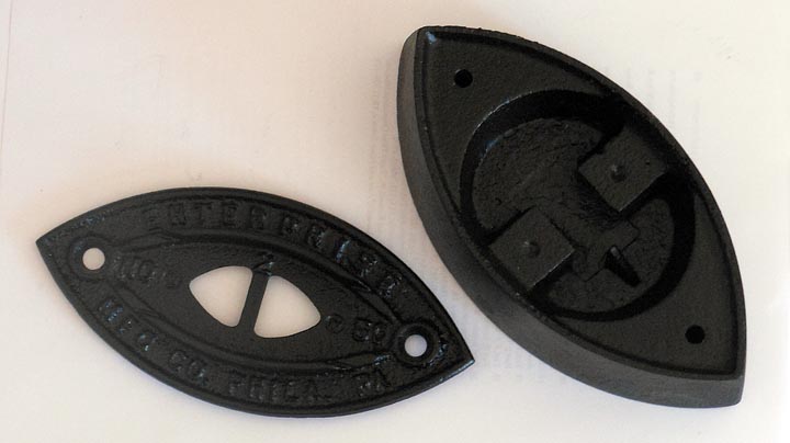
After a long time in the electrolysis tank, the bulk of the rust was removed.  The top cover was loosened up enough it wiggled but the seized screws were not freed up.  Sometimes you get lucky with rust removal by electrolysis and it will free up bolts.  In all likely hood, I didn’t let the process go to self limiting completion or possibly the electrical connection between the top plate and the base of my iron was not good.  A nice feature of rust removal by this electrolysis is that it self limits, never harming the good metal underneath the rust.

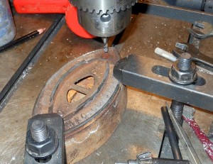
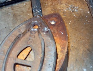
I decided  it was quicker to clamp down and use an end mill to remove the heads of the screws rather then stick the iron back in the electrolysis tank.   I use a center cutting end mill for this type of work as drill bits tend to wander and move off center.   The goal is to remove just enough metal so that you can pop off the head of the screw.  If you aren’t careful you can very easily damage the part you are trying to restore and save by drilling/milling too deeply.

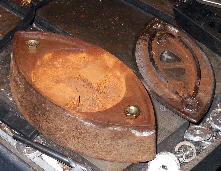
The rusty screw stubs were seized into the iron.  The best trick for removing a siezed rusty screw is to weld a nut onto the stub of the screw.  The heat generally breaks free the bolt/screw and a wrench provides plenty of torque to turn it out.  I’ve never had a bolt I couldn’t remove by this method.   Sorry, I skipped photographing the next steps.  After I pulled out the screws, I cleaned up the threads with a good quality 1/4-20 tap and then put the two halves of my iron into the sandblasting cabinet.  5 minutes of abrasive cleaning took off the surface rust that formed on the parts while they sat out in the shop.  I then immediately cleaned them with solvent and painted them with some high heat low gloss black paint.

Enterprise MFG CO No 50 Antique Coal IronI’m quite happy with how my restoration of this antique iron went.  All told I think I only spent 1 hr of actual time on this project, but it was in little bits and pieces spread out over a month and a half.  This antique iron will be a nice addition to my cool old stuff I’ve come across display cabinet.