Tag Archives: Reprap

Upgrading your 3D Printer – x-axis improvements

Upgrading your 3d printer

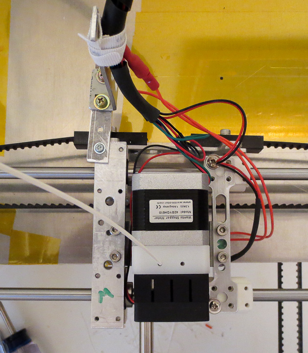
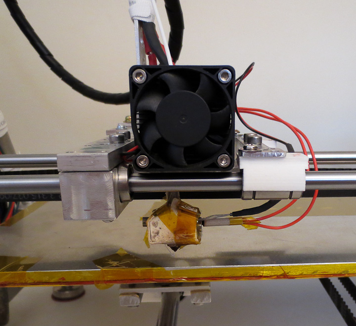
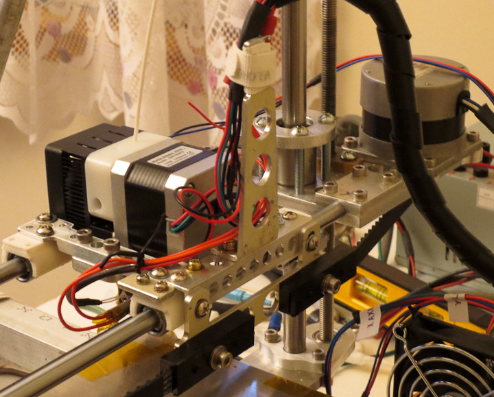
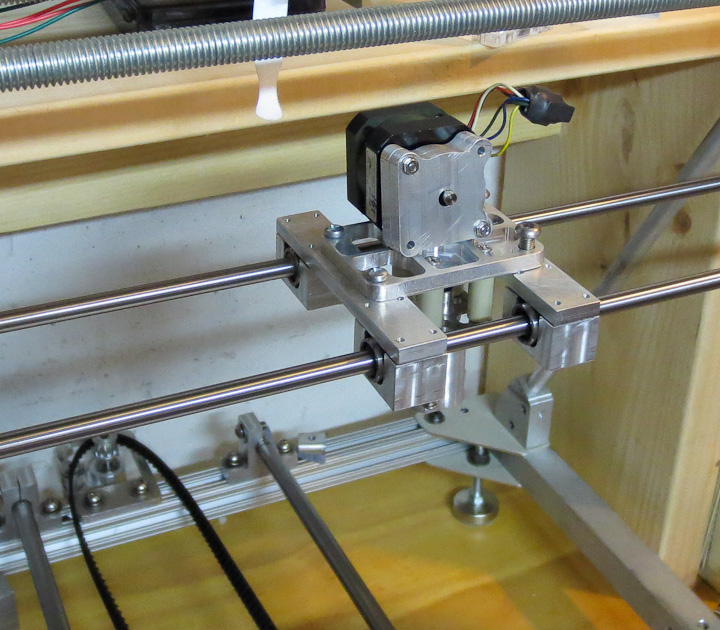
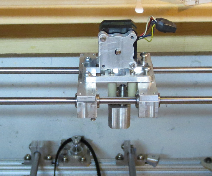
After my initial excitement of having a fully operational 3d printer waned, I used the printer to produce parts to upgrade itself. Making itself better, stronger, faster than it was before. (How cool is it that the printer can make parts to upgrade itself??) Mass of the moving components limits the speed at which they travel and increase printing time. Inertia has to be compensated for in acceleration parameters as well. In short, less mass equals faster printing. The primary goal of printing replacement parts was to reduce weight of the moving components, the x and y axis sleds.  The Z axis moves very little and the mass is much less significant.  This post focuses on the x axis upgrades. The above photo shows the x axis sled with side by side comparison of the original (on the left) and the upgraded (on the right) components.  The left side is the original proof of concept machined aluminum bearing mounts and cross brace. The right side shows the upgraded 3d printed LME8UU linear bearing mount with a skeletonized machined aluminum cross brace that also lowers the print head slightly.

3d printed LME8UU bearing mount

 As you can see more clearly in the above photo, the 3d printed ABS plastic bearing mounts are considerably smaller then the original CNC machined aluminum design.  My plastic bearing mount raps around the bearing 20 degrees beyond 180 on each side for positive retention and due to the flexibility of the ABS snap over the bearing with a perfect fit.  The plastic mounts remove 18g of mass from each bearing.  The skeletonized cross braces come in at 8 grams in aluminum vs 36g of the original aluminum parts.  I did print them in ABS at 2g part weight, but they were a bit too flexible and I was concerned with heat from the making them softer still.

3d printed LMe12uu linear bearing mounts  skelotonized x axis sled

The upgrade of the linear bearing mount and cross brace resulted in 128g of mass removed from the x axis moving components. Also the bearing mounts applied a more uniform clamping pressure on the bearings then the CNC machined design, that when over tightened resulted in bearing drag.  As is often the case when building something, you design and build using the tools you had on hand. I always planned to replace the machined bearing mounts.  My original CNC machined aluminum bearing design was accurate but bulky, ugly, and heavy.

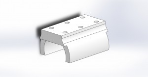
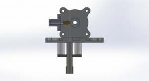
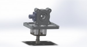
LME8UU bearing mount    

Above is a rendered image of my LME8UU bearing mount design.  The mounting holes are tapped M3 after printing and 10mm between centers. Here is a pdf technical drawing showing the dimensions : LME8UU bearing mount technical drawing.   I have added the linear bearing mount to Thingiverse.com as an STL and IGES file for others to use. Here is a link if you want to print your own 8mm linear bearing mount for a project:  http://www.thingiverse.com/thing:142243

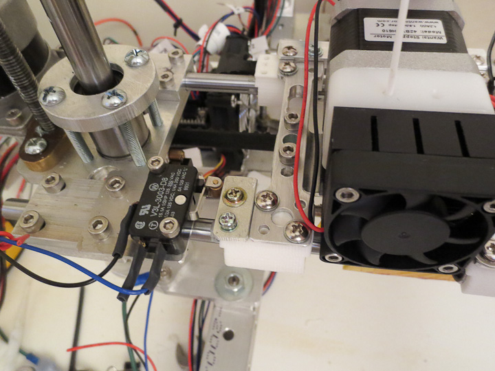
x axis limit switch plate

All was not 100% perfect with the bearing mount upgrade, I did not consider the limit switch contact points when designing them.  I added a small aluminum plate using 2 of the 3mm tapped holes to solve this minor oversight.  Eventually I’ll add a physical feature to the 3d model and print  new bearing mounts for the two limit switches.  My original purpose in designing these LM8UU linear bearing mounts was as a universal part so that I can use them in the future for other projects.

wire mounting on 3d printer

Along with the weight reduction I moved the wire support to a more centralized location on the back side of the sled.  I felt this would help reduce strain on the wires during the repetitive movement along the x axis.  I orient my parts when printing such that the bulk of the printing travel is done by the x axis.   All in all,  these improvements along with other upgrades (to be shared in future posts)  have gone a long way to increase my printers speed, reliability, and aesthetics.
 

DIY 3D Printer Progress

reprap based 3d printer x axis design

About a year ago I started building a 3D printer based on the RepRap 3D printer community. Progress essentially stopped with the arrival of spring (aka adventure season), but it is once again project season (aka winter).  My 3D printer build is approaching the testing phase for axis motion, print head extrusion quality and laying down my first builds.  This post will show the progress and provide some thoughts on the design of my 3D printer.

3D model of plastistruder cross section   Plastistruder design based on Makerbot design

Last winter I had worked out a rough design for my own plastistruder 3D print head, I made a first go at my own design but felt I could do a better job.  I had set the x axis such that it would mount a plate with 1.5″ on center bolts allowing me to experiment with different print head designs by having them be modular and easily swapped out.  The above renderings show my current design for a 3mm filament plastic extruder.  Based off the MK6 extruder from makerbot (that they apparently no longer support or sell), it was designed to use the same nozzles and 40W 12v cartridge heater.

3d printer x axis with plastic extruder head mounted

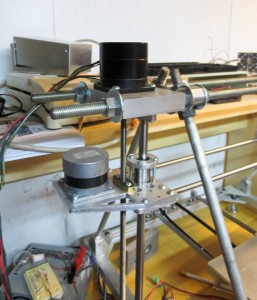
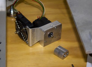
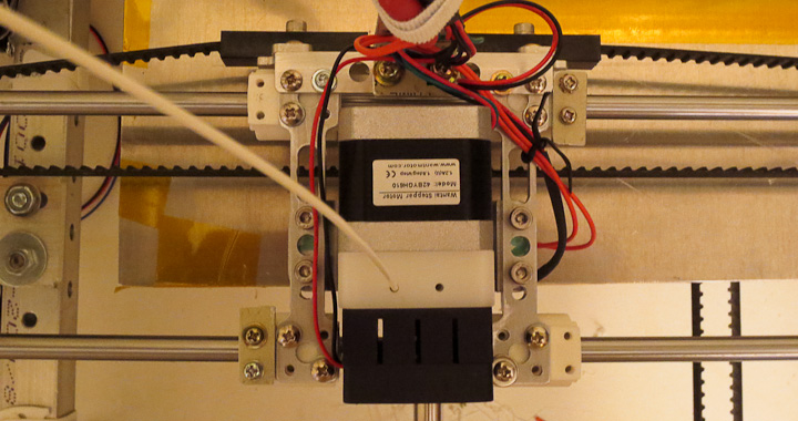
Above you can see I’ve finished the x axis mounts.  They are functional but had any weight reduction done to them yet.  The mounting plate and heat break/hot end side are done.  I plant to machine down a pc heat sink to mount to the body of the extruder opposite the NEMA 17 stepper that will drive the filament into the hot end and out the extrusion nozzle.   I found online a great little 1.75mm extruder head that I purchased here at a company called QU-BD and have ordered one since they are so cheap. I will test out both of them and compare results in a future post.

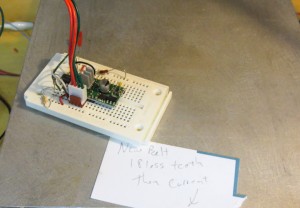
3d printer - reprap based Z-axis and x axis drive motors.    Pololu based stepper drive circuit to for 3d printer axis motion testing

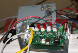
The Z axis design in my printer is basically two steppers driving threaded shafts from the same stepper pulse signal.  This seems to work well and has been done in other reprap 3d printer designs.   I am doing basic motion testing of the axis with a 555 timer as a pulse generator to drive a pololu A4988 stepper driver board.  These are great little boards for running steppers and I have used them in other projects like my cnc control box.  It’s a crude set up but does not require having a computer dedicated to this thing yet.

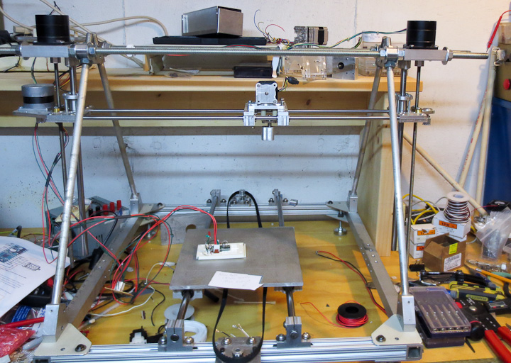
Reprap 3d printer progress

What’s left to get this thing running?  I need to order some new LX series timing belts the correct size for both the y and x axis.  Build  a y axis chassis that is lighter then the solid aluminum test plate you see in the above pictures and then mount my larger heated build surface.  Then it will be another round of electronics headaches.  Hopefully this time the supplier for my reprap electronics board doesn’t send me junk.  See my earlier post for my problems with the first Gen 6 electronics I ordered.    Then it will finally be time for testing and printing parts.  I already have a list of things to print out a mile long.  Several friends want me to print them out the standard rep rap parts. I plan to help them out. Everyone should have their own 3d printer at home.

Reprap 3D Printer progress and photos

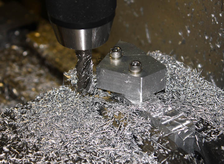
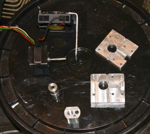
One of the corner angle mounts for my Reprep printer being made on my CNC machine.   As a kid, I was a huge fan of Science Fiction Novels, but never did I really believe I’d see the day where I’d have a robot, that would make me another robot that could then replicate itself.  I think one of the greatest things of our era is the ready access to programmable chips like the ATMEL ATmega series.  These are the processors used on the very popular Arduino and Sanguino boards.  My Reprap will be powered by Sanguino running on an ATMEL atmega eventually.   More on this topic in a later post.  Today is all about showing bits and pieces of my reprap 3d printer.

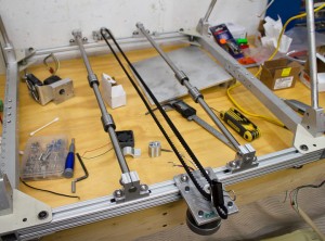
Reprap 3D printer Y axis WIP        reprap 3D Printer Z axis and x Axis drive side

The Left picture shows the Y Axis set up.  The build platform will be mounted to a carriage that runs on those four 12mm  linear bearings that are seen in the picture running through the center of the chassis.  I need to get a belt with 19 less teeth then my current or cut the belt and clamp both ends to the carriage (the 1/4″ aluminum  square in the pic).  The pic on the right shows the Z Axis as well as the drive motor on the X Axis.  The X axis will have the stepstruder printing heads on a carriage moving on 4 8mm linear bearings.

Reprap 3D printer Z axis other side       RepRap  CNC machined stepstruder print head

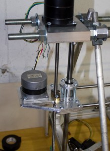
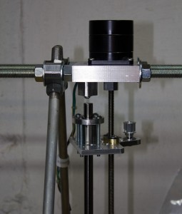
The left pic shows the idle side of the X axis as well as the other side Z axis.  I chose to go with the dual stepper motor Z axis over the belt driven dual leadscrew set up.  I have tested it with my zac built stepper driver set up run by a 555 timer pulse generator circuit to drive a pololu A4988 and it works well.  I imagine I’ll have to check for lost steps and align the printer periodically with this set up.  The right hand picture shows my milled stepstruder.  It’s roughly based on the MK6 Stepstruder sold by Makerbot with some Zac-provements.   I still need to order a heater cartridge from them and machine the shaft, heat break standoff and some other pieces to finish the plastistruder unit.  Eventually I hope to have a double extruder head set up so I can run a water soluble support material on one head and the build material on the other, or to do multicolor builds.


My RepRap based 3D printer

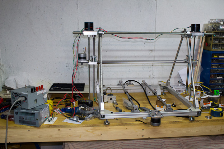
This post will catch my readers up to speed on my 3D Printer project.   It’s design is loosely based on the current RepRap Mendel and Prusa Mendel 3D Printer Designs.  My goal was to build as much of my 3d printer from what I had on hand.  I started this project back in May of 2011.  I’ve been working on it in my spare time and having my CNC Mill do 95% of the manufacturing of components for this project.  It’s been a good way for me to build CNC programming experience as well as test out the capabilities of my CNC milling machine (based on the popular RF-45 model Mill Drill) to determine Gen 2 upgrades needed to the CNC Mill.

My Reprap project is partially inspired by the fact that I had a prototype Objet Alaris 3D printer for evaluation for work for 9 months prior to their launching of that product.  It was mostly product testing and a bit of debugging for Objet but it gave me a full taste of having 3D printer access all the time.  I still have and use many of the components I printed out for the house, my zacbuilt engine driven TIG welder, and of course in the Datsun  and Mustang.   3d Printing, also often refered to as rapid prototyping, is the greatest thing to come along since the advent of CNC machining for the fabricator.   It’s often faster to design a part virtually and just print it out then to try and make it by any other means.  It’s a great way to test out crazy ideas, various styling changes, and tactile features of a design.

Reprap Gen6 electronics      reprap CNC machined Stepstruder plastistruder

My RepRap 3D printer will be driven by Gen 6 electronics.  This SMT board drives all three axis, and the stepstruder (aka plastic extruder printing head as shown in the right pic above) all in a small low power package.  My first go at acquiring a Gen 6 board did not go so well and I ended up returning it.  The board had numerous poorly soldered joints and one chip was floating off board at 20 degrees with several pins in the air.  I since decided to finish the mechanical before reacquiring another Gen 6 board.  By the time I’m ready to fire it up there might even be a better next Gen board design available.

I think I’ll close this post here,  I’ll share more about this project over the coming days to get caught up on where I am to date so I can move forward with the next steps.