It was always planned to convert the Trackmaster dozer into a standard Skid Steer Quick Attach adapter plate. This would allow implements like foIt was always planned to convert the Trackmaster dozer into a standard Skid Steer Quick Attach adapter plate. This modification would make implements such as forks and buckets interchangeable between my tractor and the Tiny Dozer.

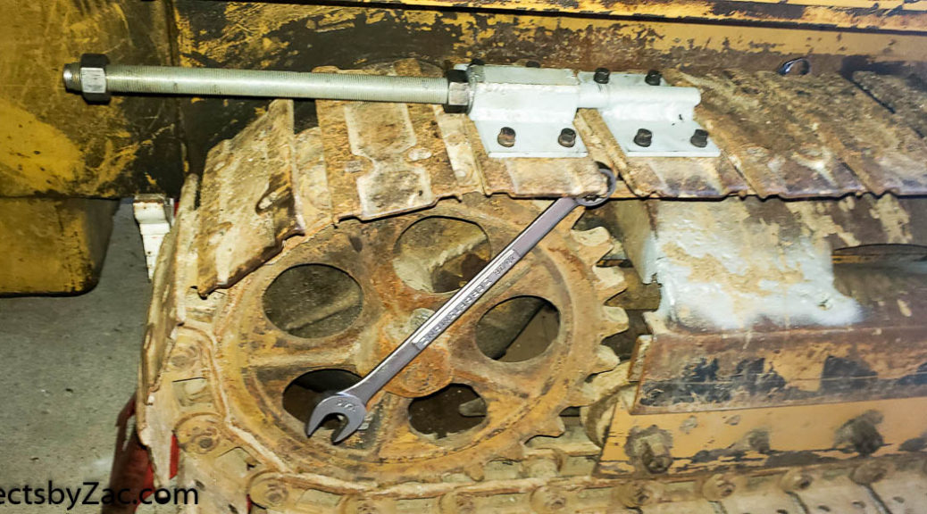
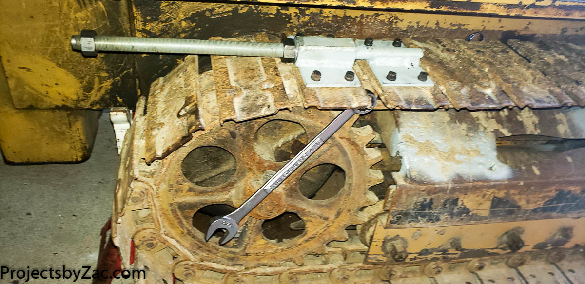
I opted for heavier supports than necessary, using scrap pieces of thicker steel I had on hand in my scrap bins. This approach will simplify the process when it’s time to weld the Trackmaster side mounting plates. I also took detailed measurements at this stage to ensure proper spacing and alignment.

I wanted to remove the brackets as cleanly as possible, so I decided to use a Sawzall for the cuts. Before cutting, I pre-ground the heavy weld fillets, which allowed me to get the saw blade very close to the plate steel reinforcing the bucket mounts. This made cleanup quicker and ensured I kept the maximum amount of metal on the brackets, which will be useful for machining and welding when I mount the dozer side plates on the Trackmaster in the future.


I use a flap wheel and nylon abrasive wheel to polish the metal, both where I plan to weld and underneath. After that, I apply Cold Galvanize spray, which also acts as a weld-through primer. The welding onto the bucket was fairly straightforward.

I used the plasma cutter to create holes in the plates where I’ll be welding around this ring to attach the mounting plates. To square up the mounting plates, I set them with a bar clamp and used a piece of scrap angle welded to the lower part of the plate to keep everything aligned. Since the bucket itself isn’t perfectly flat, there’s a slight mismatch between the squared-up plate and the bucket. As the welded area will bear most of the load, so I’m making sure there’s plenty of metal at the welded joints between the QT plate and the bucket’s reinforcing steel plate, which is 5/16″ thick A36 steel plate.

The bucket is fully welded above. I did multiple pass and turned the heat way up on the second. With the preheat from the first pass it really melted in a nice wide smooth bead all around. This was horribly stinky. I thought there was not enough paint left on the inside of the buckte to be an issue with the heat. I was very wrong. It’s cold up here in the woods of northern NH this time of year and I had to open the shop doors and get the big fans blowing and turned myself into a shivering Popsicle. I finished welding outside the next morning. The shop smelled something awful from the burning paint for a few days.
I may add a support at the bottom in the spring to help share the load of the bracket. I needed this setup to be mobile and functional in order to fix some erosion damage on my hiking/biking/tractor trail up the hill before winter set in. This bucket is about a foot shorter on each side of the tractor, so it makes it much easier to squeeze through the trees. I can use my OEM bucket, but I often end up hitting and damaging the sugar maples. By building this, I figured I could do better and support my future plans of tapping all the trees up the hill when I start sugaring commercially, all with a bit of effort now.

After some test scooping from the fill dirt pile, I’m happy with how solid this bucket is mounted. I have no worries about it bending nor any about it breaking off. I think I’ll not end up add the triangles gussets for support underneath the bottom of the mounting plate. It’s so solid I don’t think they are needed.

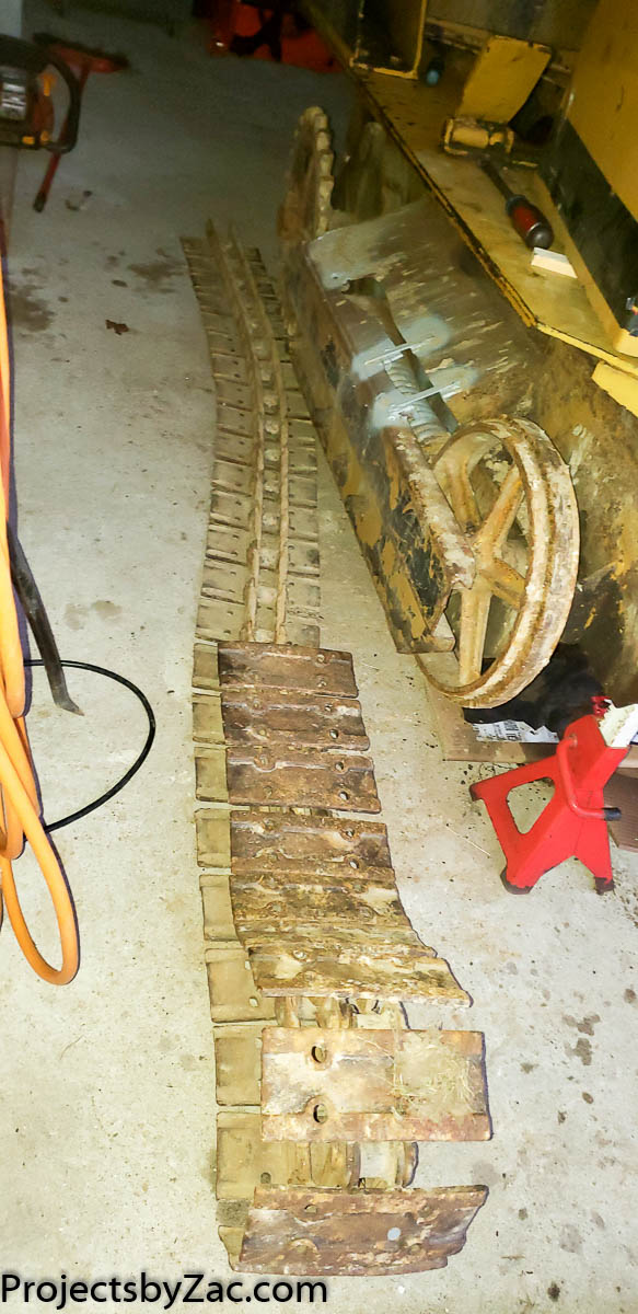
You’ll notice I haven’t posted in a long time if you’ve stumbled across my page looking for information on these machines. Progress on my tiny Trackmaster dozer/crawler loader has been slow. A lot has been done; I’m just bad about sharing updates. I hope to post more during the winter.
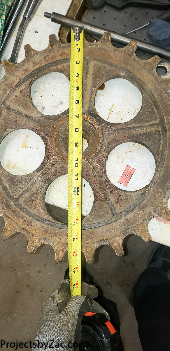
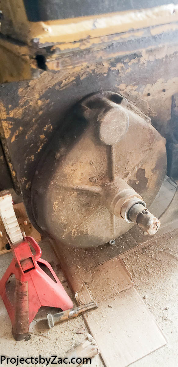
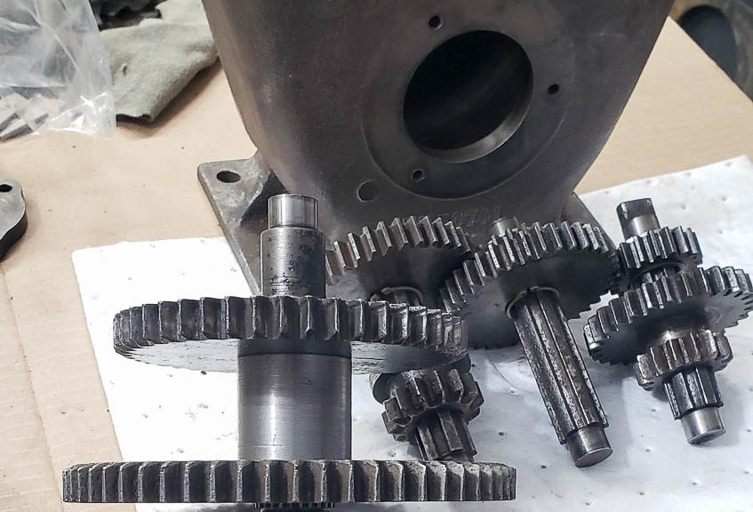
The steering clutches are rebuilt, and I’ll share the CAD files and drawings for that. The transmission is complete, with a new sprocket on both the transmission and the rear cross shaft. I’ll also provide details on the new “heart transplant” for the machine. The Wisconsin THD engine is being replaced with a new belt-driven pump. Stay tuned!
As always if you have any information on these. I would love to see them. Share a link, or photos or pdfs if you have them. I’d love to compile more info here for others to find in the future to help keep these lil machines running happily.