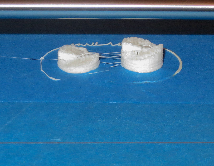
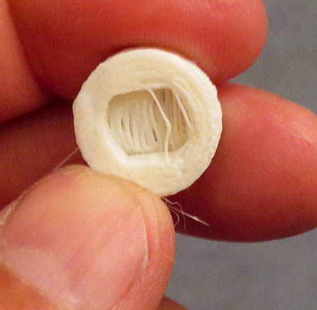
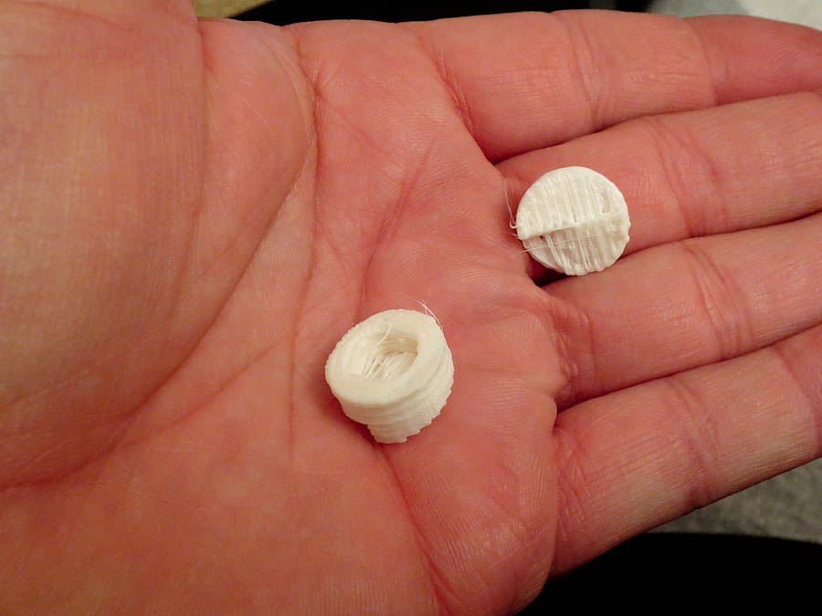
The very first parts printed on the 3d printer I have designed and built. Nothing glorious. Frankly I was expecting nothing to happen when I clicked print. I had not finished all of the final alignment adjustments needed to the build platform and frame. This print happened while I was testing the build platform heater for the first time. To see how the software worked, I loaded a small stl part file (the two pieces are a hub for a whirlyprop kids toy) mostly to see how the software processed the file. After playing with the code and making adjustments to some settings, I said to myself, “Let’s see what happens.”, clicked print and voila parts were made.
The above pictures show I still have a lot of work to do on optimizing parameters in the software code for my unique printer design. It did surprisingly well spanning the overhang with only a few loose rows of filament being out of place due to droop. The acrylic adhesive on the blue masking tape smelled something terrible after heating. This is due to some thermal degradation of the adhesive. I was happy it peeled off the build platform cleanly. The blue tape is used to help the abs stick to the build surface as it is extruded in the first layer. I had ordered some 2″ wide polyimide tape but was waiting for it to arrive when I printed these very first parts on the printer.
These parts are the very first things the 3d printer I designed and built ever printed. I was pretty excited when I saw my design in action printing. The printer is not “done” by any means. There has been a heated bed V2.0 built and installed already. The #1 issue I have found with designing and building a 3d printer that is much larger than the majority of cupecake, makerbot, reprap style printers people typically build is flatness of the build platform. More on this in my next post.
As I near completion on my 3D printer build, I found myself needing a way to drive stepper motors to quickly test axis motion (watch the video at the end of this post). To that end I threw together this low cost stepper motor drive. It is based on a Pololu A4988 stepper motor driver being run by a 555 timer set up as an oscillator. I wanted something cheap that I could quickly throw together to test the motion on the axis as well as keep handy for future stepper motor projects. I spent a little more time on this project then it warranted but now I have a great little stepper motor drive for testing future projects.
The circuit diagram above shows the basic schematics for the stepper motor drive. Sorry about the chicken scratches on paper version, but all the info is there if you want to make one of these for yourself. As always if you have any questions shoot me an email at: zac AT projectsbyzac.com The 555 timer is run as an astabile oscillator to generate the step pulses to drive the Pololu A4988 stepper driver (A4988 data sheet is here) & (Pololu A4988 datasheet is here) . If you’ve read my previous post on building a cnc machine control box based on Pololu 4988’s you know I love these little stepper drive boards. They are similar to stepstiks (drop in pin for pin replacements in fact) which will eventually run the 3d printer on the RAMPS electronics which just arrived. There are newer drop in higher performance Pololu models available now but I had a A4988 green boards on hand. To allow for variable motor speed control I used a 10 turn 10K potentiometer inline in the 555 circuit. This allows the drive speed to be varied by turning the knob. The pot I used has a digital read out. When I find a speed that works well to test a particular motor/axis drive, I can easily set it in the same speed in the future. Thanks to Adam Perkins for these 10 turn pots. I traded him some parts a few years back for a few of these 10 turn pots with read outs. This is the first project on which I have used one of them. He has a very useful webpage with great info on electronics and is my electonic project mentor from my UNH Days.
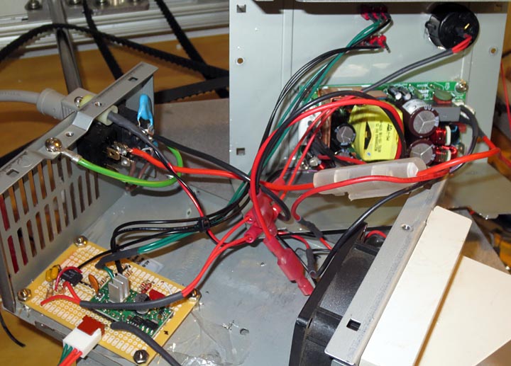
The circuit is soldered up on a small board from Radio shack. I’ve housed the entire project in an old PC power supply case. I love using PC power supply cases for projects and always have a couple on hand in my parts inventory. They have good cross flow cooling, built in fan, switch and power cords making them the perfect project enclosure. The pololu A4988 can handle up to 2.0 A with a heat sink and air flow for cooling which the power supply case fan supplies. To power this project I initially used a spare 12v 2.0A wall wart installed. The supply was noisy and it was affecting the stepper motor drive output. Additionally when it was driving the motors I could hear the cooling fan speed decrease, so it wasn’t up to the current draw needs of the motors being tested. I changed over to an Astec LPS50-M Series 60 Watts power supply I had on my parts shelf. This supply could easily handle the motor load and would provide a clean 15 volts, the supply used was an Astec LPS54-M (datasheet for the LPS54M powersupply is here).
The above photo shows the finished product. I used my CNC machine to mill out the top of the case for the pot with the readout and drill holes for mounting the power supply and the 2 toggle switches. One switch controls the direction of the motor (dir pin #14 on the pololu) and the other interrupts the signal between the 555 oscillator and the step pin (pn #13 on the pololu) allowing to start and stop the stepper motor without powering down the controller.
The above video shows the driver being used to test the Z axis on the 3D printer. I have the current control way down so when raising the axis the motors struggle a bit (the sound you hear changes from the smooth driving on the way down). I thought some of you might enjoy the video clip. There will be more videos as the printer is further tested now that I made a youtube account to host them.
Sharing some of my projects and what I've learned along the way