Category Archives: and cool stuff.

Making a DIY Printed Circuit Board (PCB) vise

Printed Circuit Board holder

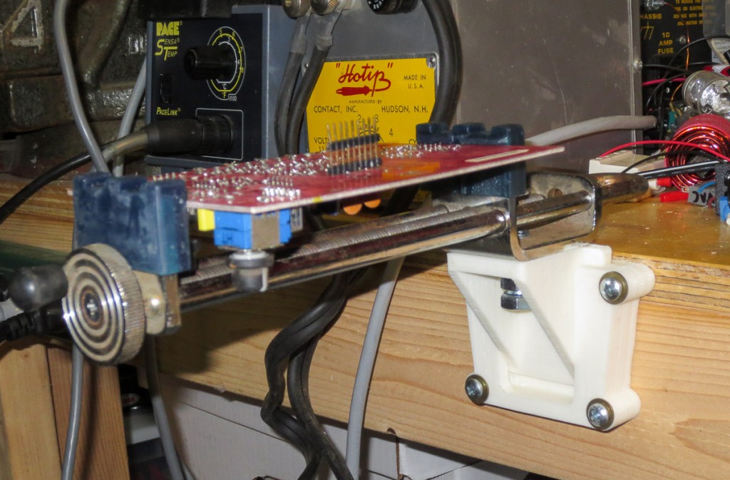
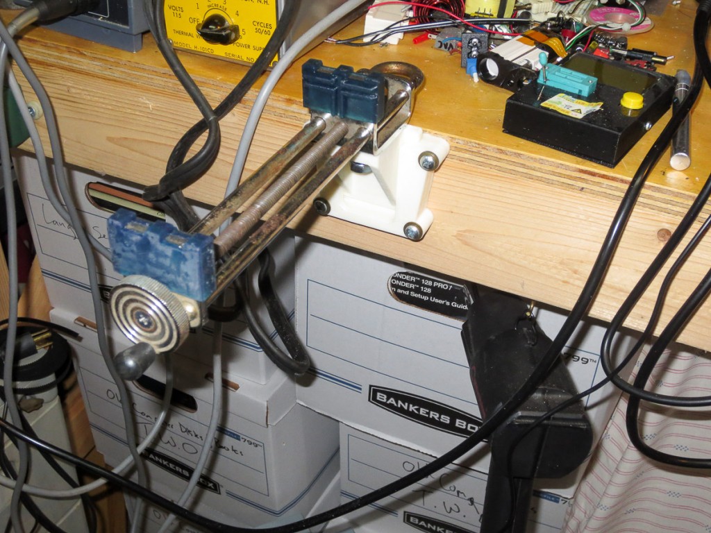
I have needed a printed circuit board vise of some sort for a while and have not found a lot of good affordable options that I liked.  I had an old Panavise style hobby vise kicking around the shop for years and I recently decided it was the perfect solution for this project.   I used two different types of 3D printers to make the parts for this project.  My printer, an FDM machine I built myself was used to print up the ABS stronger quick attach mount to attach the vise to my electronics bench.   I used a Formlabs Form1+ SLS 3D Printer to print the PCB holders/grips in a tough 3D printable material that was launched a few months back, appropriately called “Tough”.

 Printed Circuit board Clamping fixtures SLA printed -3321        Printed Circuit board Clamping fixtures SLA printed -3318

The backbone of this project is an old wide opening Panavise.  These were a staple of the hobby world.  I routinely see them for <$1 at flea markets and yard sales.  I had this one kicking around in my metalworking shop for ages.   I must have  picked up somewhere for $0.25 as it still had the yard sale sticker on it.   These originally came with a variety of low quality rubber “grips” and some sort of mount, often a poor quality plastic suction cup thing meant to quickly attach to your presumably smooth workbench.  I gave away a handful of these to fellow hobbyists a couple years ago but this one survived the culling, and I’m glad it did.

Formlabs Touch SLA Printed grips

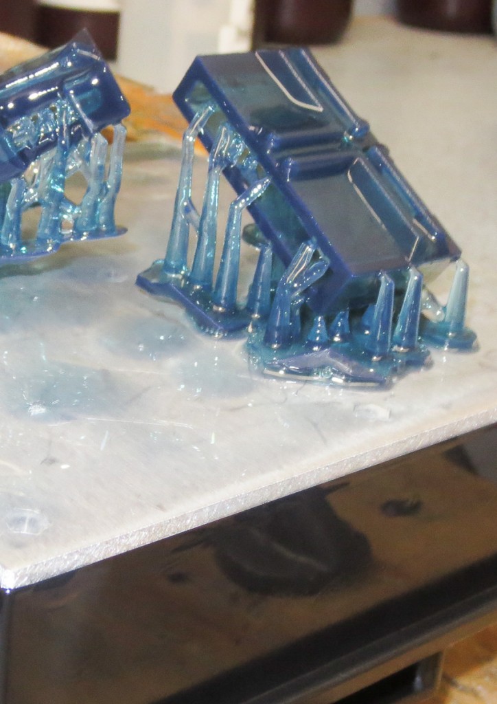
All of my previous posts on 3D printing used my machine.  I now have available to me one of the other types of 3D printing technologies, SLA.   This type of printer grows parts out of liquid resin, typically with a laser or projector system.  I’ve been using a Form1+ model SLA printer.  It’s a pretty fantastic machine with amazing resolution and detail.  There are also some great materials with different properties that I can not print on my Zac built FDM type 3D printer.   These include the Tough material I used to make the PCB grips for the old panavise clamp I wanted to put to good use for this project.  Formlabs tough resin is, well tough.   Meaning it’s not brittle like may SLA resins.  It also has a good feel to it and excellent mechanical properties for things like vise jaws.  The vise jaws are shown on the build platform after printing.  These are designed to slip over the metal “jaws” of the old Panavise I am using.  If you want to print out your own set of these jaws, circuit board vise jaws for panavise vice clamps.


FDM printed Vise quick attach mount

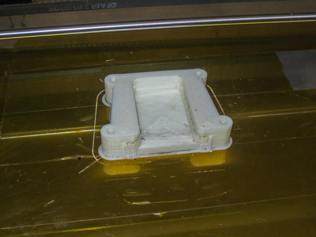
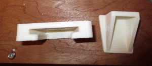
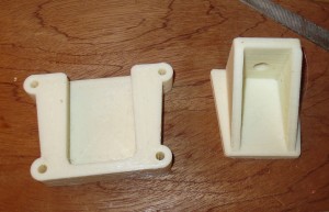
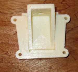
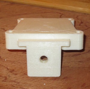
The other piece of the puzzle I needed to make this project work was a way to quickly attach and detach this vise from my electronics bench.  I do not plan to use this vise all the time.   It would be in my way a lot, meaning it needed a quick attach system.  I quickly drew one up and printed it out on my personal 3D printer.   I print in ABS and for this application this material is perfect.   Thequick attach vise mount for workbench.


081715  PCB holder 3d printed vise inserts-3551      081715  PCB holder 3d printed vise inserts-3550

Both parts of the quick attach vise mount printed out in a few hours.   The mounting bolt on the panavise clamp is threaded 3/8-24.  I ended up using a bolt and a nut to tighten the clamp to the mount.

081715  PCB holder 3d printed vise inserts-3553            081715  PCB holder 3d printed vise inserts-3554

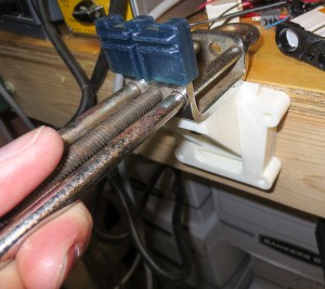
As you can see the two parts interlock.  there is a taper that locks the vise in place, but comes free with a quick tap upwards from underneath.

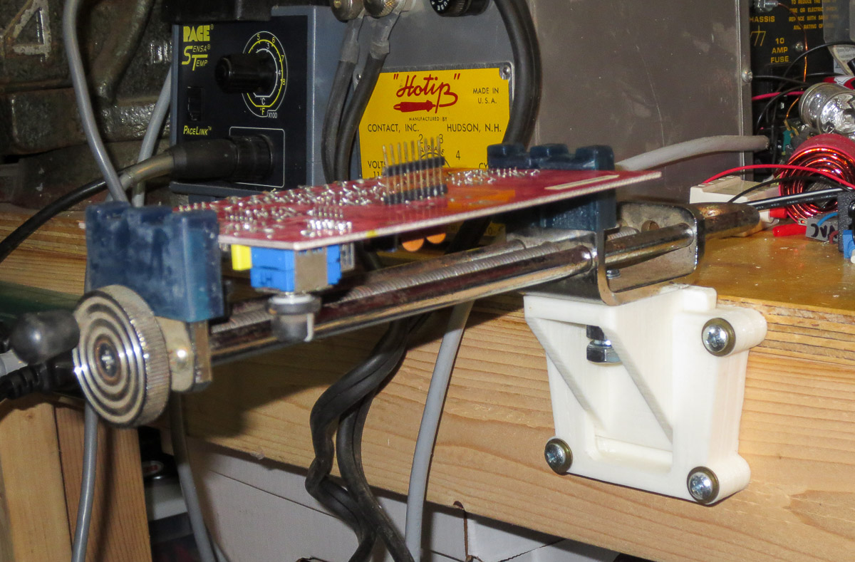
Panavise quick attach workbench PCB vise

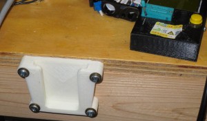
Testing the location on the bench.  Can you see what’s wrong with my design.  I had a home ‘doh! moment when I saw what I did.

081715  PCB holder 3d printed vise inserts-3556      Printed Circuit Board holder

081715  PCB holder 3d printed vise inserts-3557

The thing I did wrong, is design the quick attach mount with the upper screws at the top.  The problem is that this design screws in edgewise to the plywood top of my workbench.  It is never a great idea to screw into the edge of plywood and expect it to hold.  This application is low force so I think I will be ok.  A better design would have the upper screw mounts 0.75″ lower, I will change my part files for others who want to use my design for themselves have a better design.

Printed Circuit Board holder

081715  PCB holder 3d printed vise inserts-3558

081715  PCB holder 3d printed vise inserts-3561

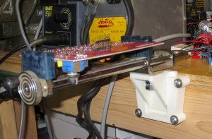
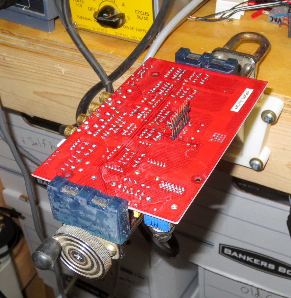
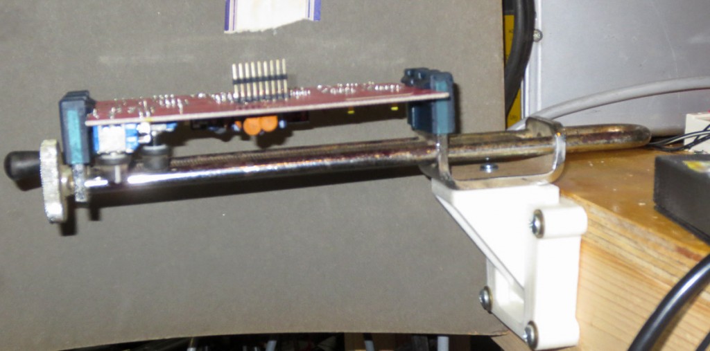
The above pics shows the vice holding an audio amp circuit board I needed to do some testing on.   As you can see the new PCB vise works great.  It can also hold smaller circuit boards vertically with the middle groove I added in my third and final iteration on the design.  I have used this great circuit board vise a handful of times already and I love it.

More on my other PCB holding and testing stations experiences in a future post when I have time.
My Custom Designed 25W RMS ipod/mp3 Player Speaker Sound System

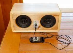
mp3 speaker dock sound system

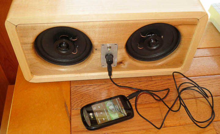
I’m big on recycling and feel the highest form of recycling is to re-purpose and reuse things that would otherwise be discarded.  This project is built largely from re-purposed recycled components. It’s fabrication used 3d printing, cnc machining, electronics, and woodworking.  The inspiration came about when I was visiting my buddy and he asked me to help him move a giant older DLP television out of his basement to the curb.  Realizing it was going to the dump, I asked if I could take a few useful parts from it.  Originally planning to only grab the connector plate off  the back that I needed for another project, we ended up taking the TV apart and I recovered the power supply unit, speakers, some circuit boards and the connectors I was originally after.  Research online showed that the speakers were really quite nice units, fully shielded with decent Theile/Small specifications.  There was an onboard self contained amplifier chip in the TDA family that was easily desoldered and built into a small stand alone audio amp.   I had been wanting a small nice powered speaker unit for some time and  I now had all the parts I needed to build myself one.

Desktop Active Speakers -0811      Desktop Active Speakers -0810

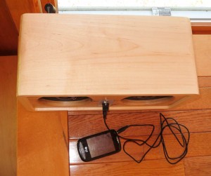
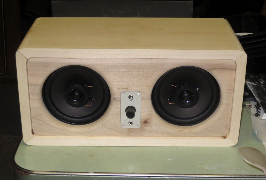
I went with a slightly retro design for this unit.   I didn’t really reference anything outside of some basics, like the golden ratio and standard speaker enclosure practices.  I’m very happy with how it looks and sounds.  I think it’s very attractive, fitting well with the rest of my things.


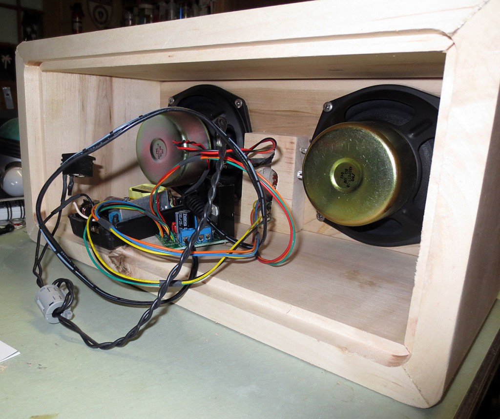
Maple desktop powered speaker system - insides

Before buttoning it all up there was several rounds of testing out the electronics, switches, power supply, etc to ensure everything worked correctly.  In the end I removed the screw terminals on the PCB and soldered the wires directly worrying that they might come loose with vibration from the music.


Desktop Active Speakers -0635        Desktop Active Speakers -0751

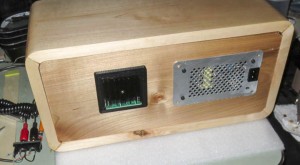
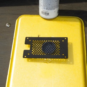
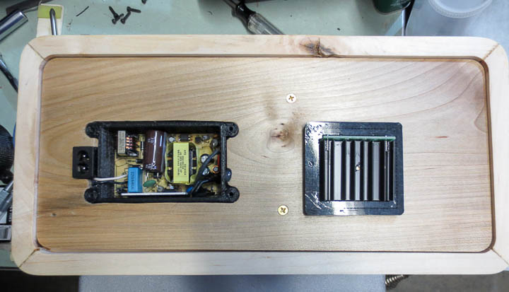
The amplifier housing on the left is 3d printed in ABS, as is the power supply housing on the right in the above photo.  I went with a machined metal vent/cover plate milled on my converted CNC machine.  I’m a big fan of Krylon’s ultra Flat Black paint and used this on the back cover for a nice matte black finish.


Desktop Active Speakers -0749

The power supply is a standard unit I kept from some piece of electronics that was out dated.  A few minor modifications, remote plug, switched line inputs and an active LED on the front panel all were done the power supply.   Then I designed and 3D printed a case to mount it safely into the speaker unit.


Maple desktop powered speaker system

The lighter wood for the outer bodycame from a storm downed maple that I milled into lumber three or so summers ago and dried.   The front and back boards came from a log off a riverland maple my lifelong friend’s father let me take when he cleared some off his property a couple years ago.  Even the front plate is machined from aluminum recycled from an old PC case.


Desktop Active Speakers -0814

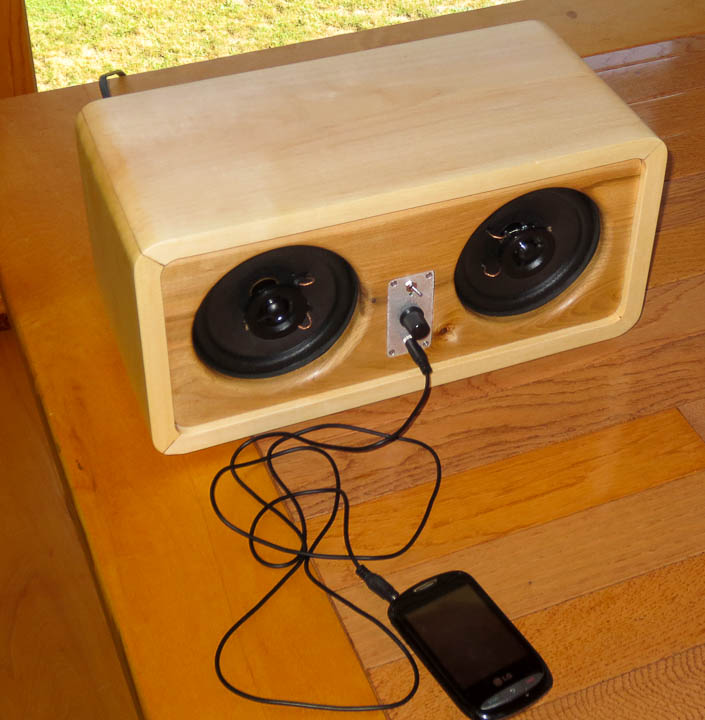
The finished speaker unit sounds amazing.  I missed a few pictures in the build process. The inside is fully sealed with a divider keeping the two chambers separate.  I also used some polyester batting as internal dampening to increase the effective internal  “volume” of the speaker enclosures.  This unit survived a 48 hrs continuous stress test without any issues.  I love how it looks as well as how good it sounds!

Ducted fan designs, an early project sneak peek

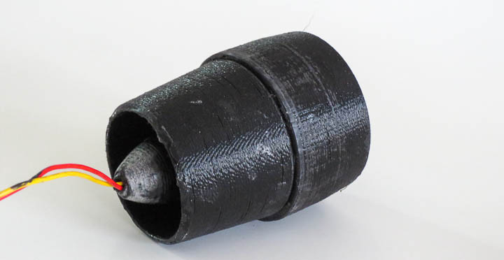
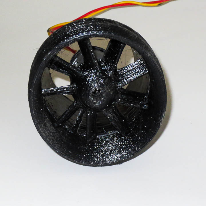
3d printed ducted rotor aircraft engine

This post is an early sneak peek at a project I have been working on in my spare time.  I showed a friend who stopped by and he told someone else an I was pestered to share pics and a video.  I have been experimenting with ducted fan thrust generation with a planned application.  As for what  that application is…  Well it is not ready for the world yet and I will let you use your imagination.

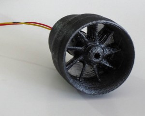
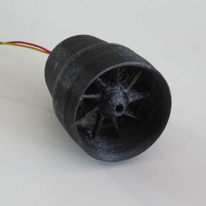
thrust generating ducted rotor     3d printed ducted fan thrust generator

Mostly eye candy at this stage of the game, I have tested 3 different rotor designs without getting into complex blade geometries to date. I have primarily been focused on printing rotors that have little wall clearance and hand finishing them to minimize the gap between the duct and rotor blade.  Research papers I have read shows that this area is critical to ducted fan efficiency and design.

ducted fan design 3d printed-9400

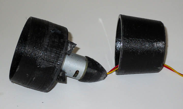
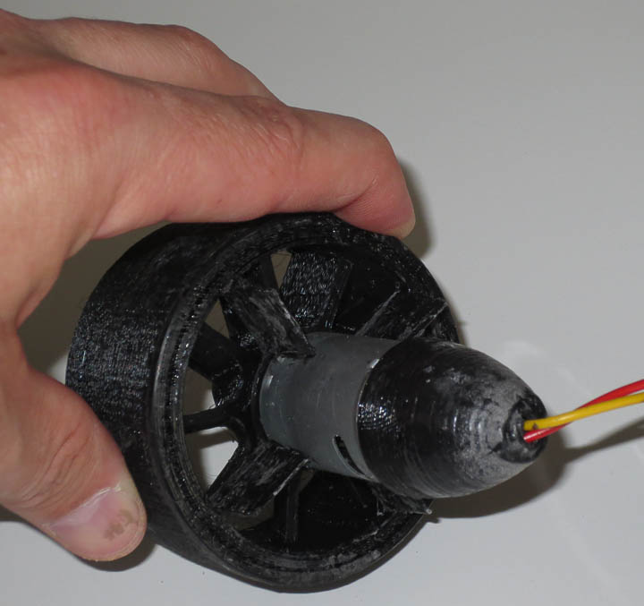
I am currently using a set up with a friction fit on a taper to lock the two halves together so I can get at the motor.  This little bad boy screams when she spools up.  In the shop it sounds like a mini jet engine starting up.   I am working on test platform speed a controller for it using an Arduino nano and components..

rotor design for ducted fan

You can see that this needs lots of cleaning and smoothing before final thrust measurements.  I plan to put it through an acetone bath treatment and then do a bit of hand finishing to smooth out the inner walls to reduce any drag from the 3d printed irregularities.  Eventually I’ll make a rotor balancing jig to fine tune the balance on the rotor.  Future iterations will likely have continually reduced rotor mass to decrease inertia.  I am testing behind a 1/4″ polycarbonate shield in case of catastrophic failure.

ducted fan design 3d printed-9401Here’s one with my hand to provide you with a sense of scale.  I will try to get a video of it spinning at moderate speed.  Without a speed controller I’m reluctant to limit test the high speed operation at this stage of development.  I will put a video up here later this weekend if I can find time.