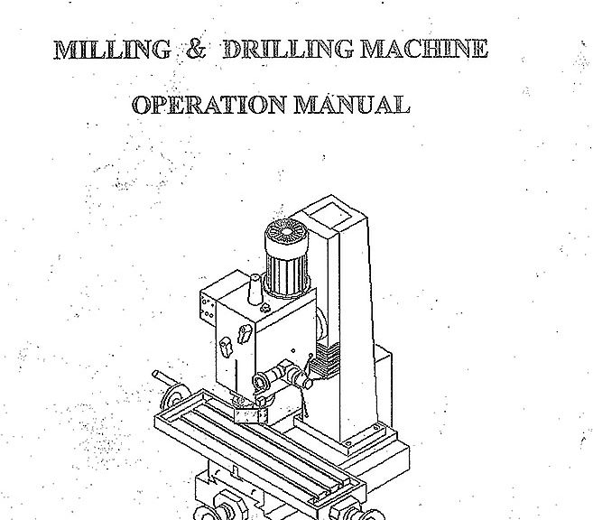
I couldn’t find this online, found close but not exact. After lots of looking I found the original paper manual which I scanned to make this file. Truth, I didn’t clean it up, but it’s all there. I’m hosting this primarily for my own personal future reference but I also hope it helps someone else out with one of these great machines. I have ~3000hrs on mine most since it’s CNC conversion many years ago (link to posts) and a bearing is finally going. It’s nice of them to list the bearings part numbers out in the manual. Time for a rebuild for my overused and highly abused mill.
Download link to the user manual for my RF7045 mill drill clone in pdf format below.
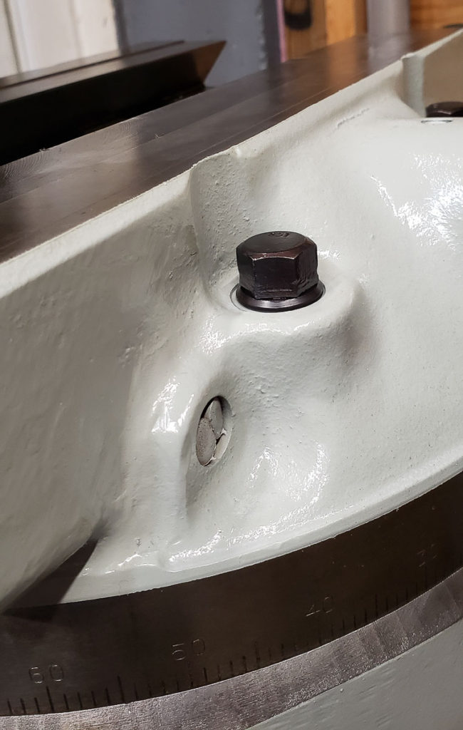
It often happens as you are working on rebuilding or restoring some old iron, machine tool, etc that you come across a blind bearing in some machined pocket. These can be a real bear to remove, especially if as in the case of my 70’s era Trackmaster bulldozer it’s a nasty mess in need of restoration. You can see the blind bearing in the top middle of the photo below.
Trackmaster dozer transmission housing by d-Fab Engineering a devision of Fruehauf Corp Route 202, Montgomberyville, Pennsylvania USA
I looked for a puller tool, they make them but even cheap ones are still a bit pricey for a single pull. This bearing, like all of the others was trashed, so I knew I wasn’t going to be reusing it, and as such I went with the tride and true method. I’ll share with photos below the details of one of the best ways to get a stuck bearing out.
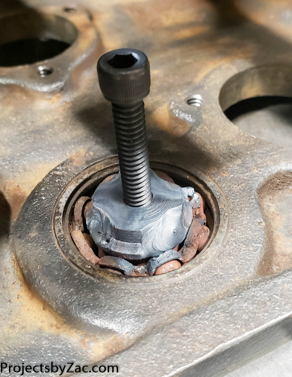
Blind bearing removal Tip Step 1: make a threaded bushing for the ID of the bearing, or use a nut that fits the opening well enough.Blind bearing removal Tip Step 2: insert your a threaded bushing and weld it carefully to the inner race, you can mig or tig depending on what you have.
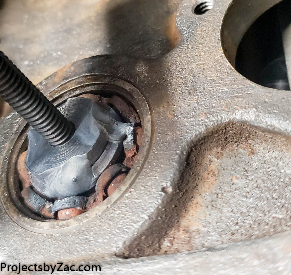
Blind bearing removal trick step 3: After welding your nut or insert into the inner race, thread a good quality bolt into the center. Be sure to let the entire thing cool to room temperature slowly. Bearings are hard, you don’t want it to shatter.blind bearing removal trick step 4: screw in your bolt, and press out the bearing from the blind pocket. Even if it was stuck before, often the heat from welding and cooling will allow it to press right out. Never discount the force generated from an inclined plane wrapped around a cylindrical axis in any pressing operation. *Wear eye protection. Every now and again the bearing explodes into shards of sharp metal that fly everywhere.
Blind bearing puller complete, you’ve got a nice clean pocket ready to install a fresh new bearing into. Best part is you haven’t risked nicking or cutting into the sidewalls with other methods like dremmel/chisel.The inside of the 3 speed bulldozer transmission has cleaned up relatively well. A bit more work cleaning and it will be ready for the reassmbly.
Summing up my favorite blind bearing removol trick in steps:
Make a threaded bushing for the ID of the bearing, or use a nut that fits close enough.
Place in or on the bearing with the threaded hole centered as best you can.
Weld in place, and let everything cool fully. (you don’t have to go nuts, three good spot welds spaced are usually enough)
After it cools, thread in a good quality bolt with some crease or oil on the threads
Start turning and let the screw press out your blind bearing.
This of course requires a welder, but many of the tools I looked at cost as much as a cheap HF welder. Go buy the welder, you will be happy you purchased it rather than a fancy one time use blind bearing removal tool.
I’m skipping ahead in regards to order things happened in the rebuild as many friends are interested in this particular topic and I do not want to write to each of them explaining how it works.
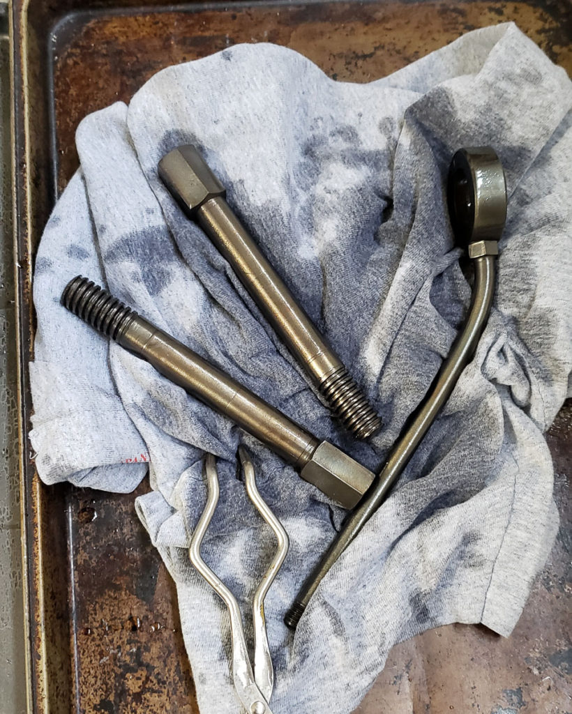
Freshly refinished Turret Bolt in Black Oxide. Contrasts nicely with the Industrial Light Machine Grey Paint.
In addition to restoring the castings and mechanicals on my Bridgeport Milling Machine I scrounged late last year, I needed to restore or replace the hardware. Replacing hardware can get expensive quickly. The hardware on the mill was all very servicable, but very ugly. I opted to clean, polish, and refinish all of the hardware. I am a huge fan of Black Oxide or Blued finishes on steel. While not suitable for exterior applications, this helps keeps hardware used inside from rusting prematurely. Plus, as you see in the photo above, the black hardware contrasts nicely with the Industrial Light Machine Grey paint I used on the castings after stripping them.
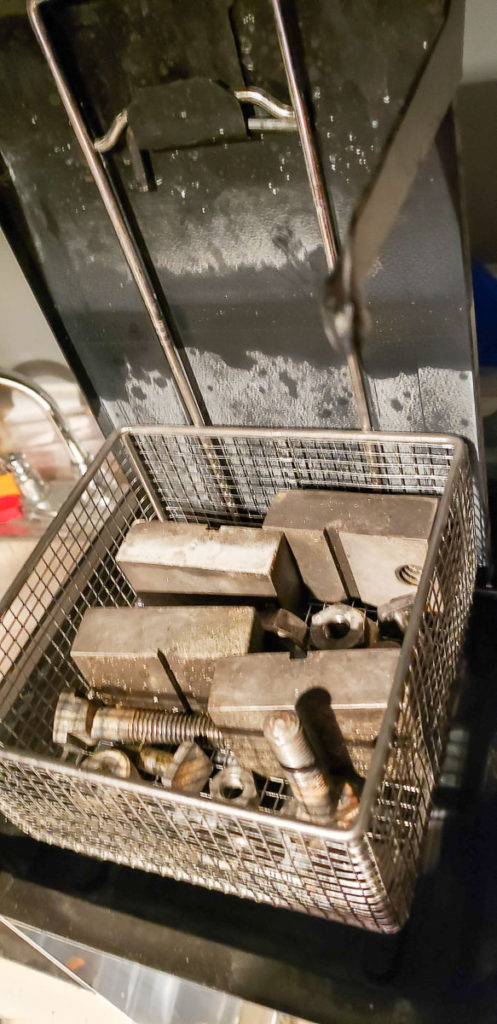
Degreasing hardware in a FormWash with Purple Degreaser
Refinishing hardware is a bit labor intensive. Thankfully the Bridgeport uses relatively few nuts, bolts, and washers in assembly. I start hardware restoration by bulk degreasing and washing all of the parts in an old FormWash which agitates the bath and has been modified to heat the de-greaser to better clean components. I use either Simple Green or Castrol Superclean without dilution as a degreaser which works well, especially heated up to about 50C. You can degrease a surprisingly large number of really nasty dirty parts and engine bits in this before you need to change out your degreaser.
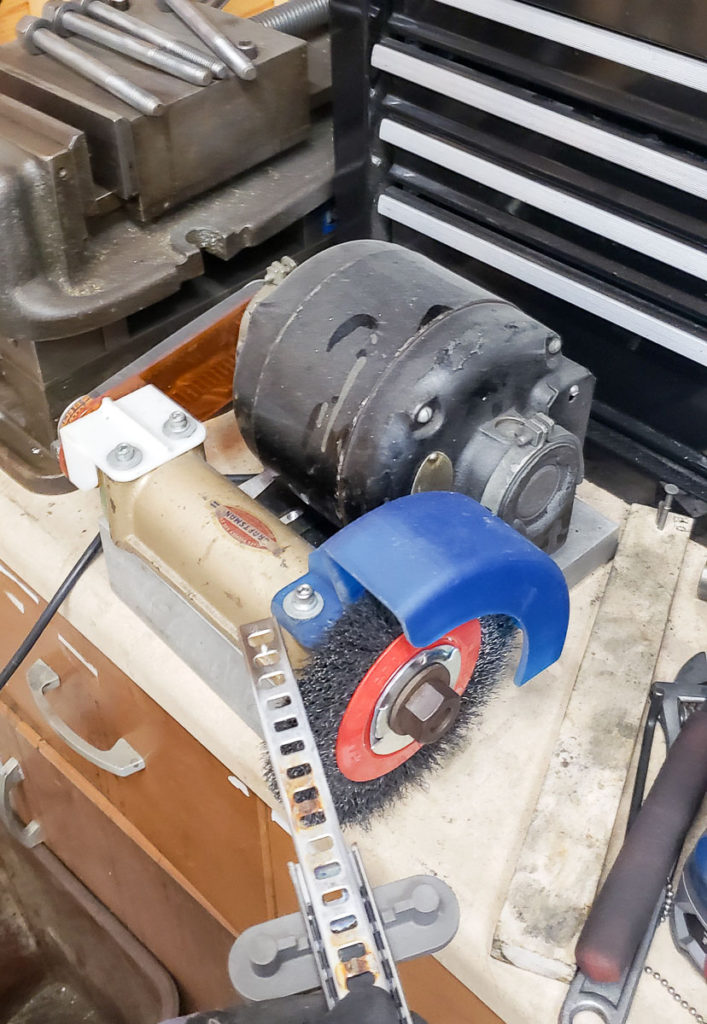
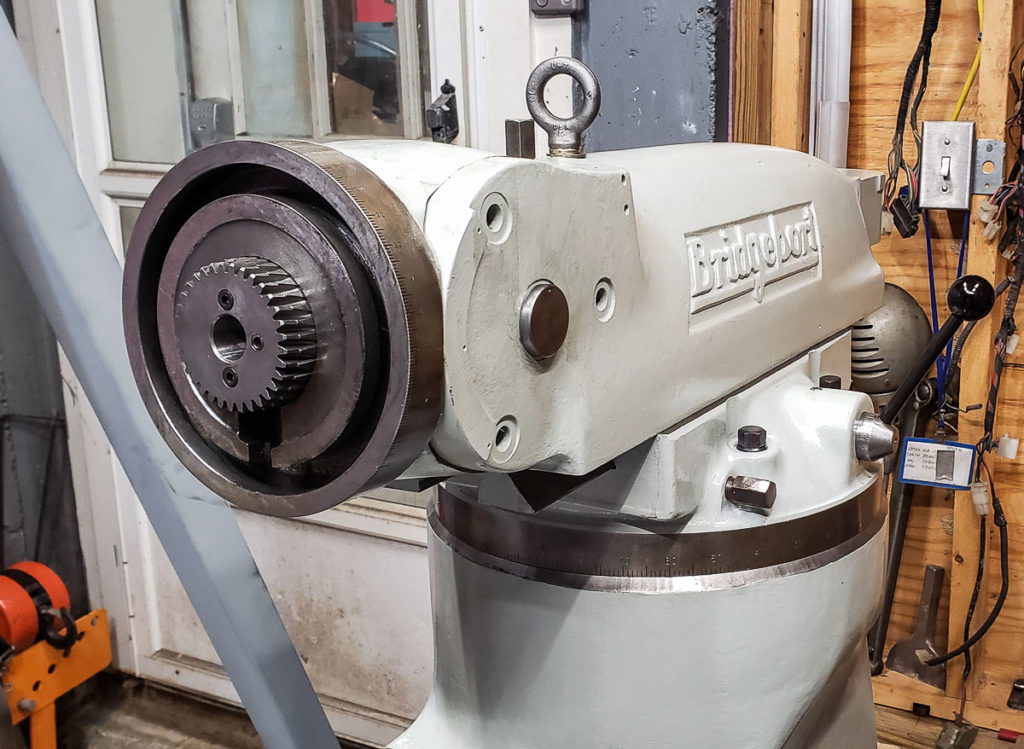
The small wire wheel buffer I made from mu parts piles at the start of this project. It’s been priceless in restoring all of the smaller hardware by polishing it to shiny bare metal.
After degreasing, I spend a few minutes on the wire wheel buffer I built polishing the hardware to shiny bare metal. I’m not looking for mirror finish on the parts, but I do ensure no grit, grime, rust, dirt, or burrs remain. I will touch up dings and “Gorilla wrenching” marks with a fine double cut file and rebuff when I find them. I run taps through the nuts to ensure the threads are cleaned out.
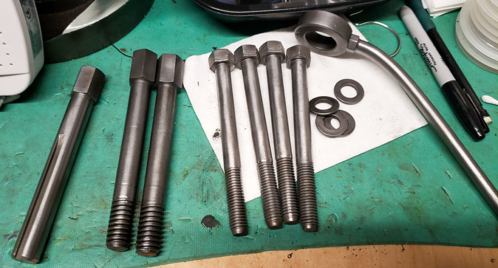
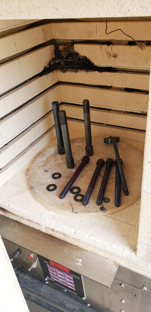
Post degreasing and wire brush polishing the bolts are shiny bright metalPreheating the furnace to 300C (550-600F) for black oxide coating of steels.
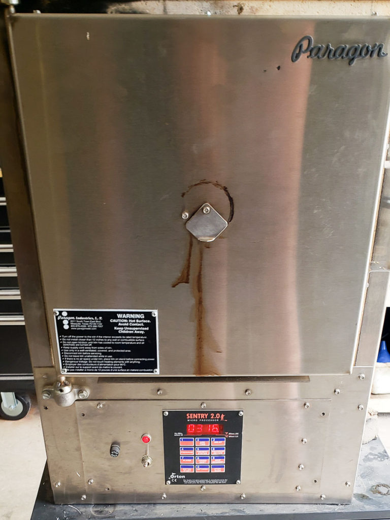
After cleaning and prepping the hardware the next step is to preheat your furnace to 300C. I have a very nice Paragon furnace I scrounged. It was wrecked when I got it due to some experiment gone horribly wrong. I managed to restore and fix this furnace to almost perfect working condition with very little cost. It’s quite large inside and capable of holding temperatures up to about 1100C.
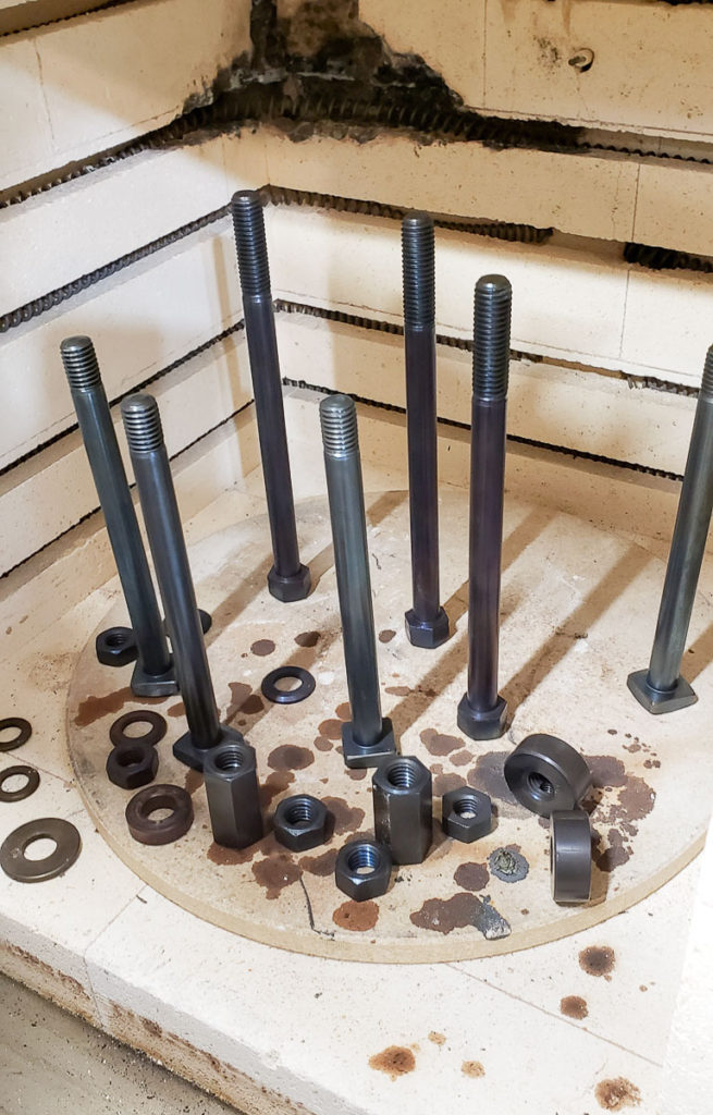
Hardware in the furnace turning black.
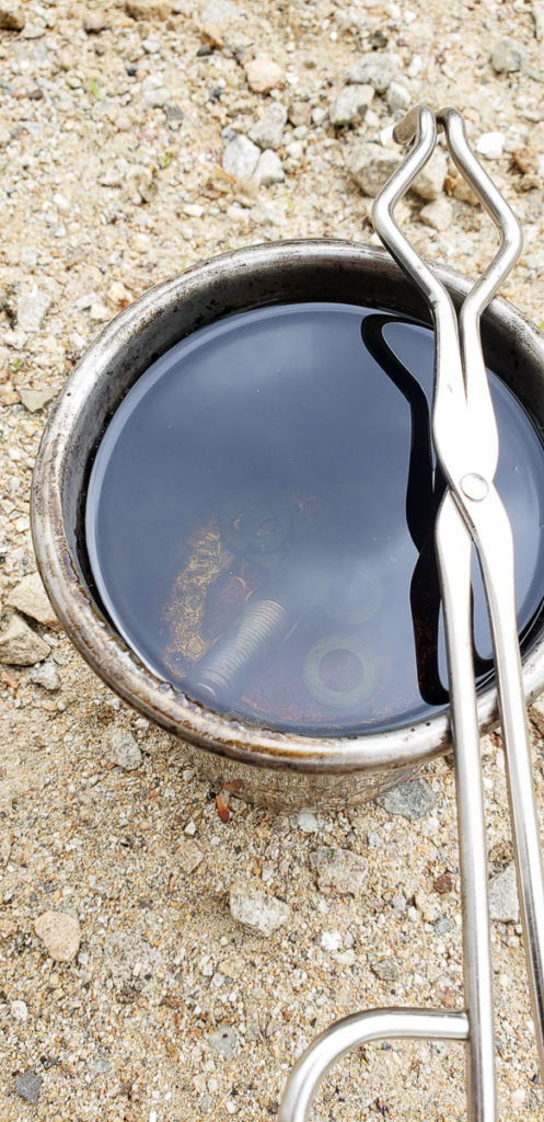
This is not the modern process of blackening steels that uses salt solution baths. This is more of the DIY, slower old school method. The process involves heating your clean, dry, parts at 300C for an hour or two, then you dunk them in a nice oil. I am a fan of Canola (rapeseed) oil for this dunking. You can repeat these steps if you want a darker heavier finish. This process leaves a nice hard blue-black finish on your steel. The alloy and part size and shape do affect this process a bit. So all of your parts may not end up quite the exact same shade of black. Dwell time and contaminates can cause differences in color as well.
Use a metal container for your oil bath, 300C steel will melt right through most plastic containers.
I originally saw this process in a video restoration of an old Vise that my buddy Brian shared with me. This is that vice restoration video which is wonderfully put together: https://www.youtube.com/watch?v=U2jNeObHnZY The video is well worth the time to watch as it is very well done.
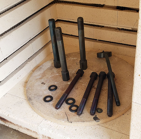
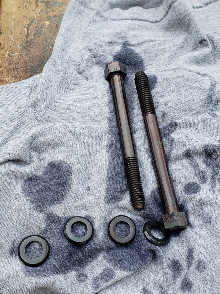
Finished parts come out very nicely with a hard black oxide coating. They look like new.There are slight differences in the black levels on different parts. Some due to alloy, and some due to part mass/dwell time I believe. I have not extensively investigated this process and the effect of variables like temperature and time have on the resulting finish.
The newly blacked parts get sprayed with a solvent wash to remove the canola oil residue which might varnish over time. I then liberally coat them with Vactra way oil or a nice 30W motor oil before installing them back into the mill.
You can see the black hardware contrasts and looks great with the light grey paint on the freshly restored castings.
On the mill the freshly blackened hardware looks fantastic. I am glad to share this trick. It is a nice quick way to give old hardware a new fresh look in a restoration. I like that it doesn’t require multiple baths of nasty caustic and salt solutions compared to the modern industrial process of hot or mid temp chemical conversion coating to black oxide.
Another batch of hardware in the furnace for treatment.
While restoring my Bridgeport Series I milling machine I reached a point where I needed a gantry crane to lift off the largest component from the mill. I shopped around online but could not find exactly what I wanted/needed in terms of size and capacity. This unavailability lead to me building one. Building yourself a gantry crane has the big advantage of being exactly the size you need. I wanted mine to be able to lift 2 tons safely, and fit with only an inch or so to spare inside my shop’s ceiling.
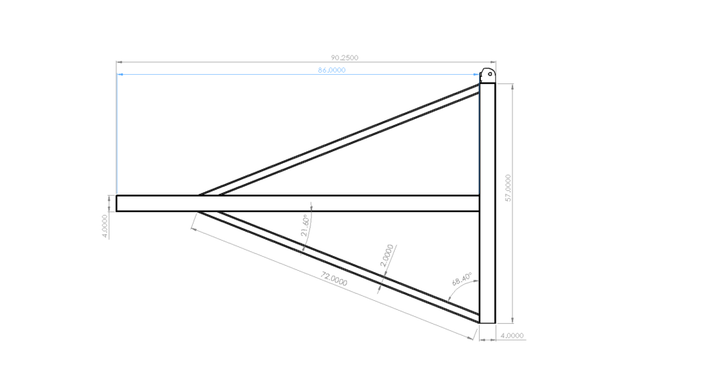
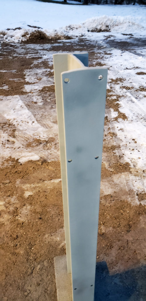
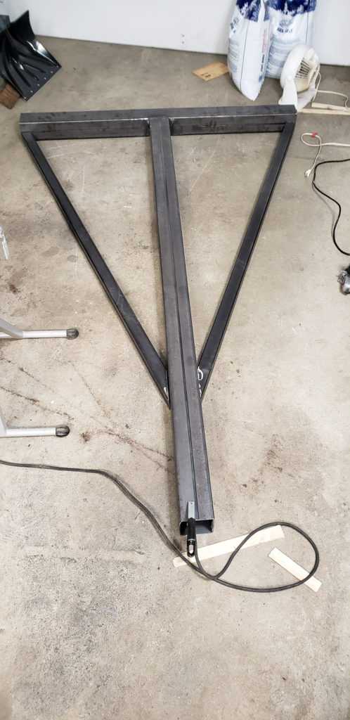
Drawing of the upright with dimensions. I used 0.120″ wall square steel tubing for the upright construction.
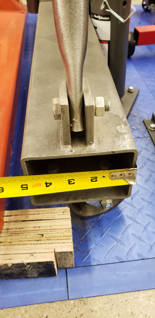
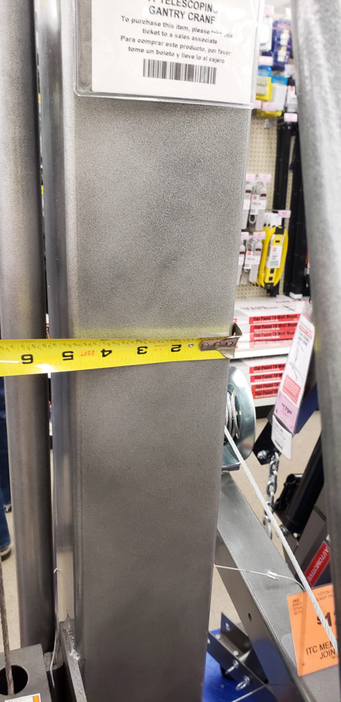
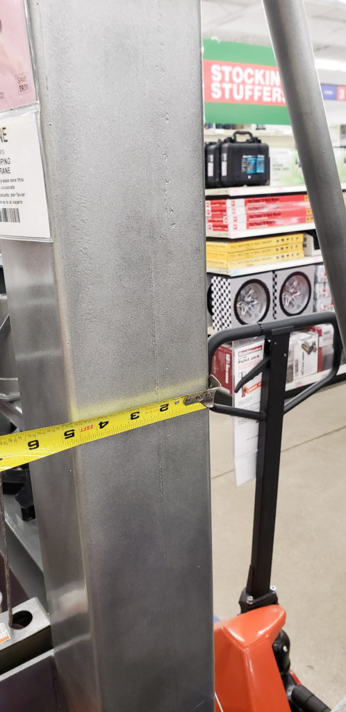
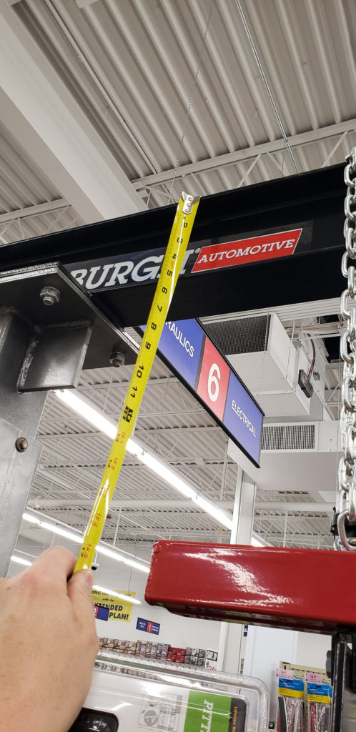
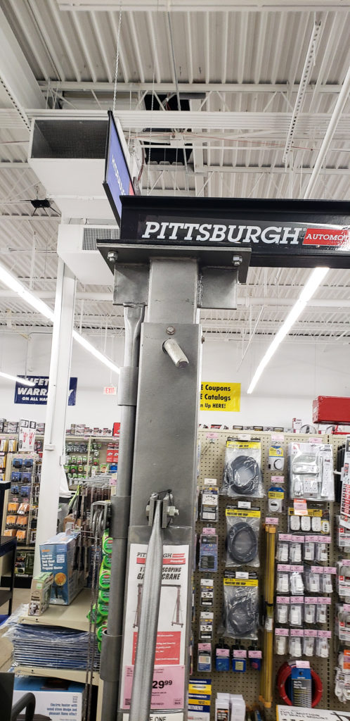
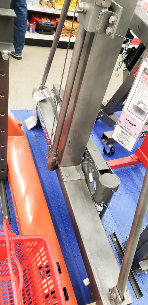
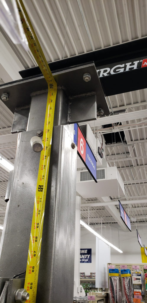
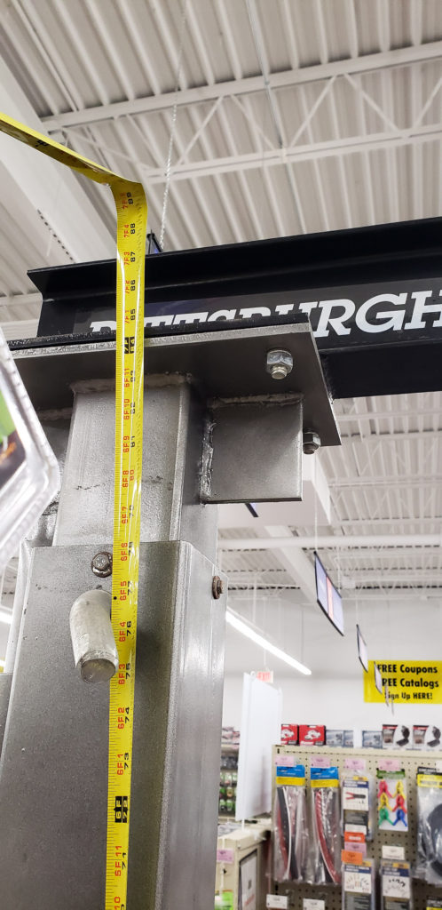
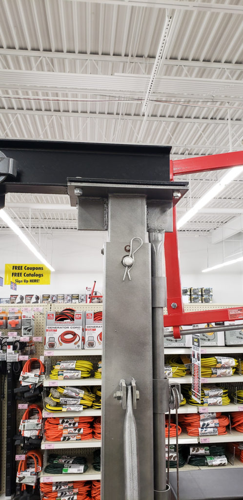
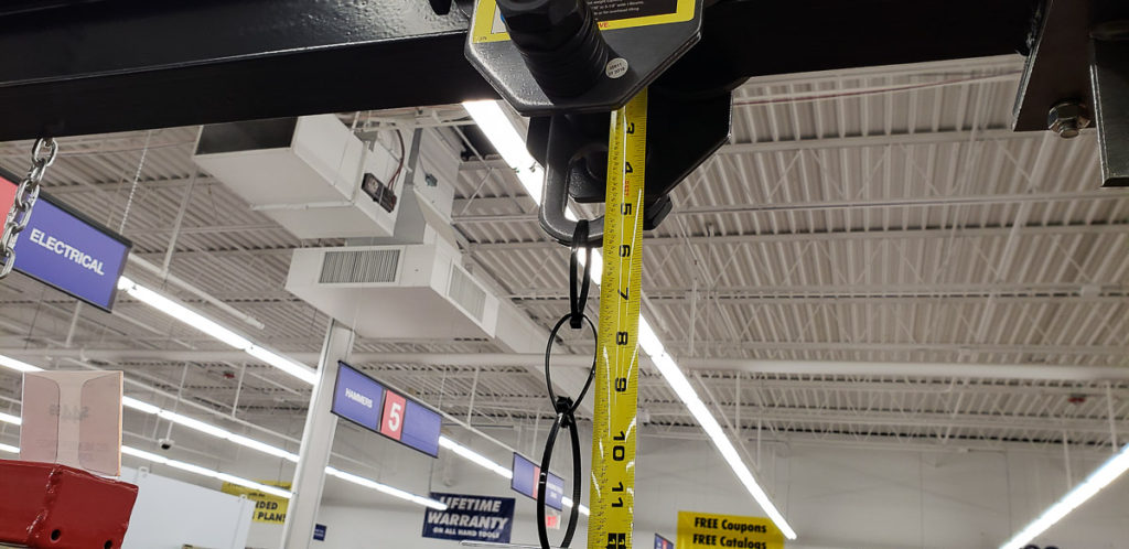
Harbor Freight does offer a reasonably affordable Gantry Crane. With a 25% off coupon you can get it for just under $600. I went and measured it to see if it would meet my needs. You can see my photos of measurements taken on the HF gantry crane in the gallery below. Turns out it would need a lot of modifications to be useful to me. I decided it wasn’t worth buying it to modify as making one would be less work and less money out of pocket.
After CADing up my proposed design, I went to my favorite steel supply shop Cohen Steel to purchase the necessary materials. All of the upright tubing is 0.120″ wall square tube. I ended up getting a short 4ft cheap W8x13 beam from their drop rack saved myself money. I plan to buy a 9ft beam length in the future to use this gantry crane to lift heavy things into the back of my truck.
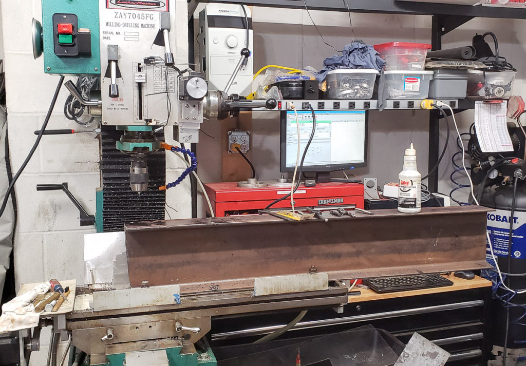
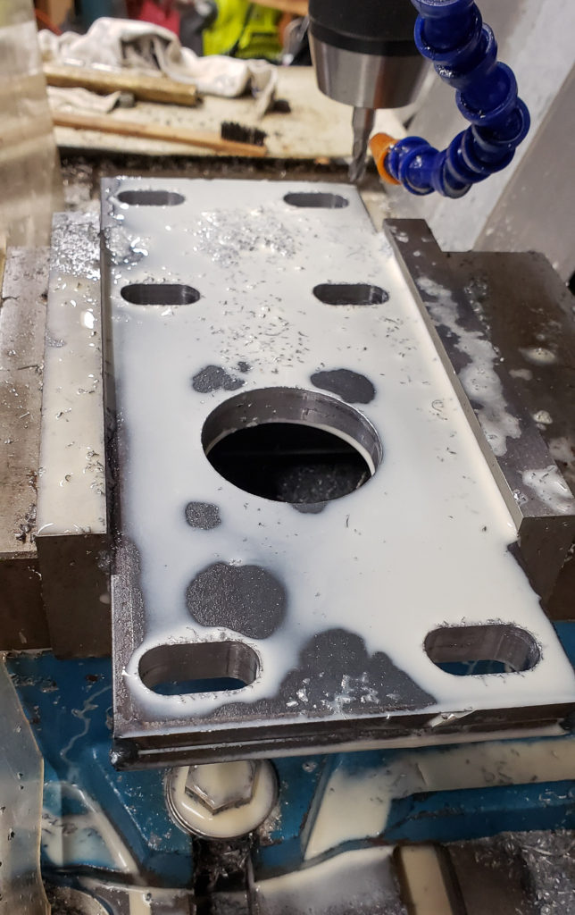
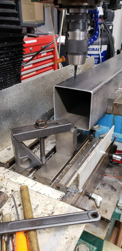
CNC machining the mounting threads into the Gantry Crane Top Beam.
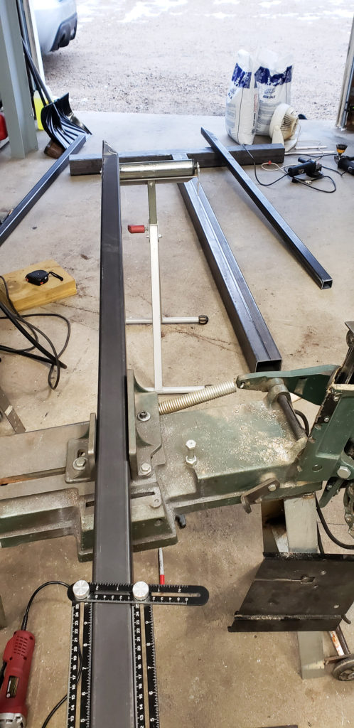
I machined the top brackets for the uprights as well as the beam ends on my CNC mill. The beam machining was a bit ridiculous, but I was lazy and this was the easiest way. You can see that most of it is hanging off the CNC mill’s table in the photo above. I had to pull the vise to do the machining.
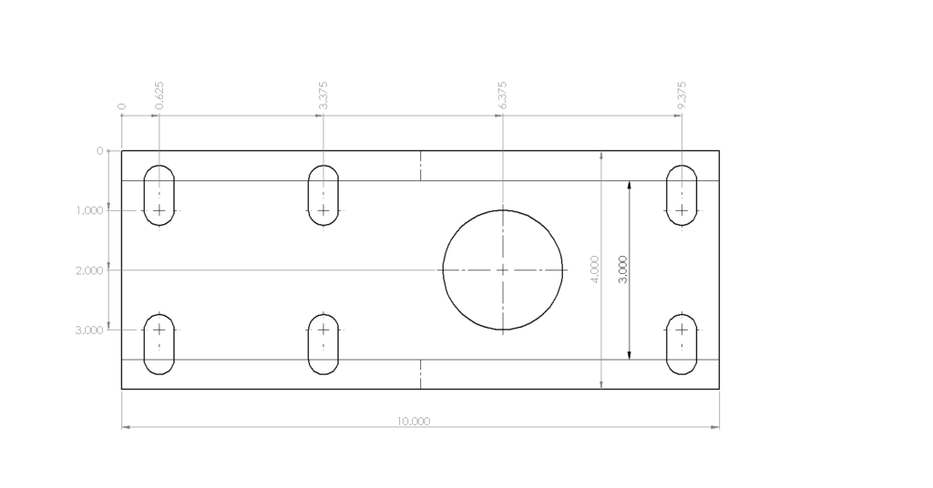
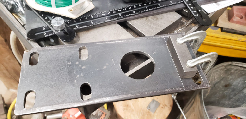
This is the mounting plate drawing for the top of the uprights.
Above is the drawing for the mounting plate on the top of the upright. It’s certainly possible to make one of these with just a drill press and carefully center punching and laying out the hole locations. I used slots in my design as I will likely use different beam sizes when I go to a longer beam. I wanted to leave some wiggle and adjustment room to make assembly easier. The big hole in the bracket is there for alignment. I plan to weld locating rings or disks onto the ends of the beam to aid in assembly. The design of the upright mount is is such that I can add an extension to raise the beam height in the future if I need an extra few feet. Bolt on extensions are a lot easier than going for a telescoping upright design.
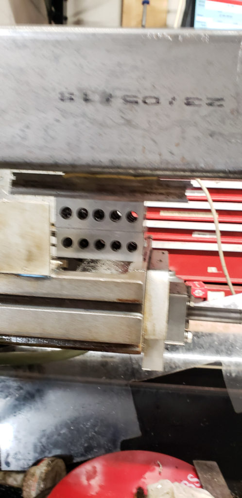
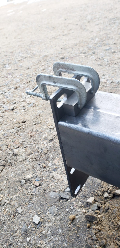
CNC milling the top upright mount brackets to secure the beam in place.
About the only trick I used in this build was tack welding the corners of two 0.25″ thick upright top mounting plates together before machining. Doing both at the same time saves some setup and machining time. If you look carefully you can see the tack welds in the corners. I later rounded the corners by hand and removed the tack welds separating the plates.
There was a lot of cutting on my band saw, grinding with different wheels, and welding to build this, but not a lot of tricks outside of being careful. WIP pics in the gallery below for your viewing pleasure.
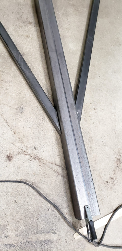
Cutting everything to length before welding it together allowed me to assure everything matched
Machining mounting holes for casters onto the bottom of the upright cross pieces
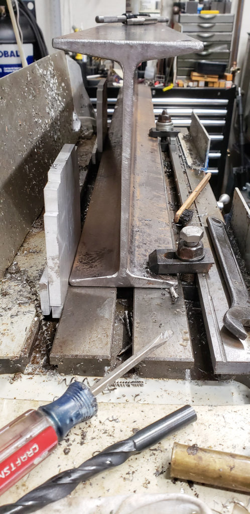
Supporting the beam on the mill table
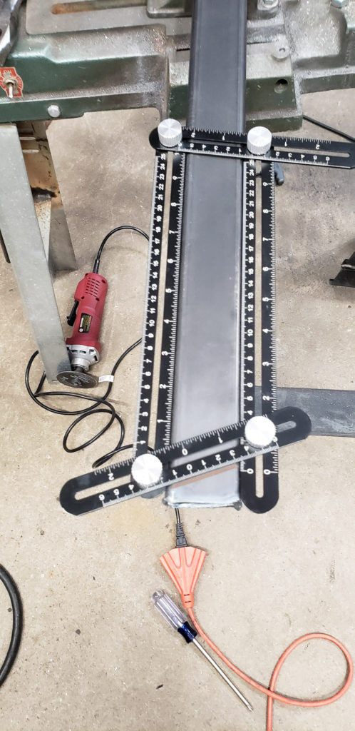
This is a handy little measuring tool for making duplicate angles in this type of assembly
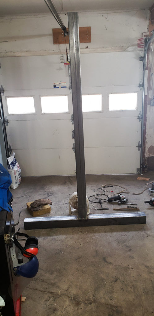
Welding the upright
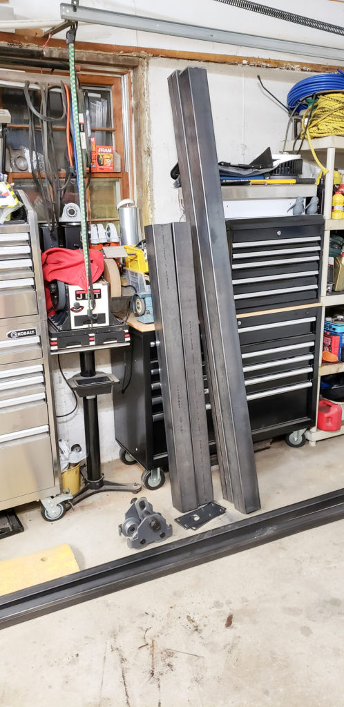
Can’t open the garage doors with the upright standing up. With the beam on it only clears my shop cielings by ~1.5 inches
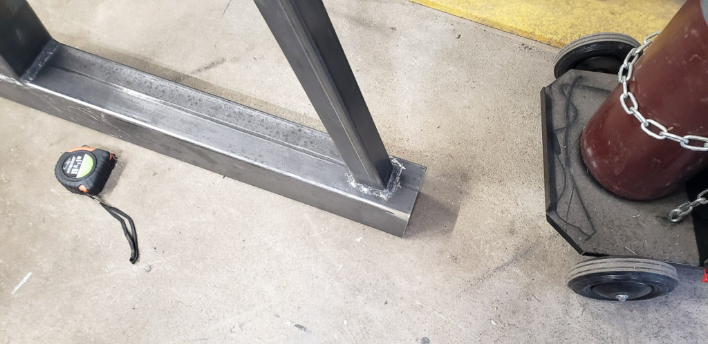
When you are working long hard 16 hour days, trying to get a job done in a weekend, you make mistakes. I was working fast, and so focused on getting the base cross piece perfectly square that on the second upright I ended up knocking it off center. Thus the two sides are not exactly the same. In function this doesn’t change much, however it does irk me to have made this mistake in my exhaustion.
My whoops on this project, I didn’t notice it until way too late to fix it. Since it doesn’t affect the performance or use of the gantry crane, I left it to remind myself to be more careful in the future. This upright has the center post off center by about 2 inches.
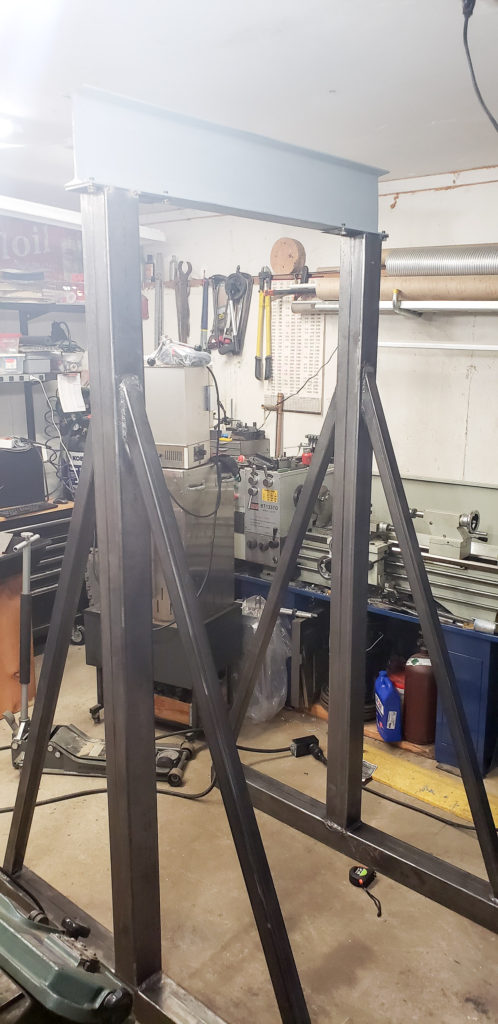
Below is the picture of the gantry crane set up for the first time. I was pretty excited to get it together. It was late Sunday night and I still had a bunch of welding to do. I did a test fit without the top plate gussets or welds being complete to ensure it was going to work before I finished up the welding.
First test assembly of the Gantry Crane
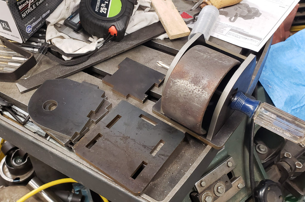
For now, the uprights have a wheel on only one end. I used wheels from an old 4 ton jack I had scrapped a few years ago. You can see my water jet brackets and a fixed wheel test fit in the photo below. The axle is a piece of 3/4″ steel shaft on the Gantry lift. The screwdriver was just to hold it for photographic purposes. To date I have used my machine skates for the other side of the Gantry crane uprights in order to wheel it about under load. Eventually I’ll mount the spinning caster type wheels that you can barely see in the bottom left of the picture below to the other end of the uprights.
Test fit of the water jet cut brackets for the wheel mount. I designed it so I could tilt the upright and roll it about somewhat easily. Each upright is over 100lbs, not so heavy I can’t carry it around but it’s easier to be able to wheel them around.
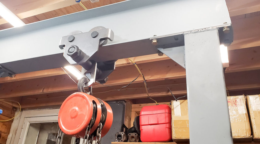
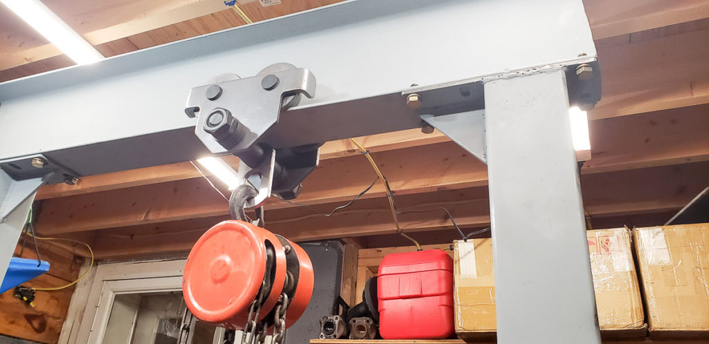
For the lifting I have a 1 ton Chain Hoist and a Harbor Freight beam trolley. I regret using the trolley. I will eventually buy or make a static clamp type mount for the chain hoist. It tends to roll when in use, which I don’t like. Alternatively I may just make clamps for the edge of the beam to stop the trolley from rolling.
Beam trolley on the Gantry Crane, in use lifting the knee off the Bridgeport.
The gantry crane lifted the knee off my Bridgeport with ease. It allowed me to remove it safely, lifting it straight up slowly so I could ensure there would be no damage to the precious precision machined surfaces of the ways. You can read more and see photos about this first use of the gantry crane in my previous blog post: Bridgeport Milling machine Restoration: Part 3 Challenges of taking apart the mill
If you end up building a gantry crane and my post was helpful please share a picture of your project in the comments. I would love to see what I might have helped inspire you to build. Cheers!
Sharing some of my projects and what I've learned along the way