Category Archives: CX500 Cafe Racer Build

Honda CX 500 Cafe Racer custom exhaust build part 2


custom exhaust CX500 Cafe Racer

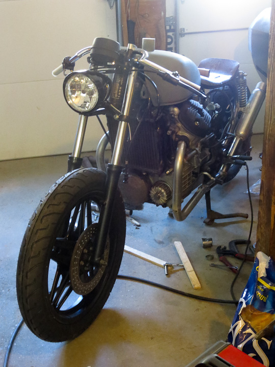
It has been a while since I last updated my CX-500 Cafe Racer project.   There has been lots of progress on the bike, but very little posting. I hope to get caught up on sharing this project here on projectsbyzac.com in the coming weeks.   In my previous post I shared some of the trials and tribulations involved in building a custom exhaust for my cafe racer bike.   I started with the back half of the exhaust as I knew where I wanted the muffler to be placed on the bike.  This post shares the issues working with the front section of the exhaust from the cylinders to the previously built back half.

 CX500 exhaust Cafe Racer build    CX-500 Cafe racer exhaust 01

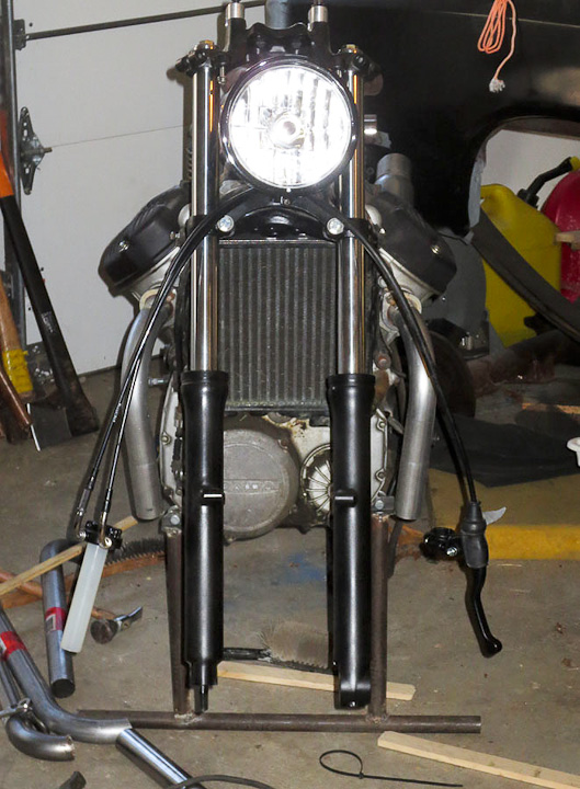
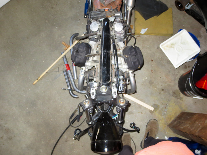
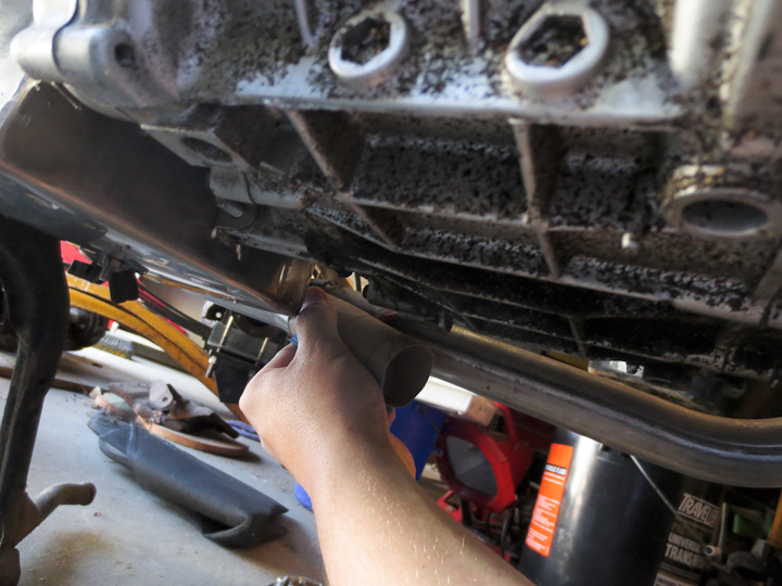
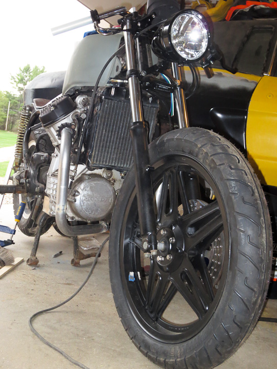
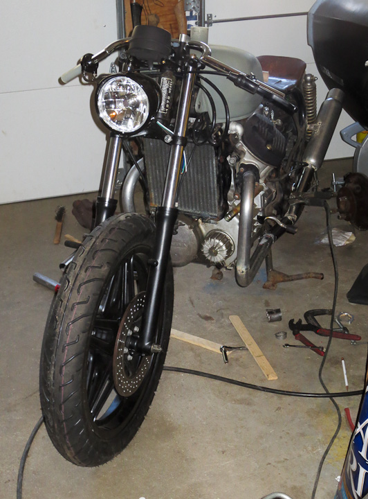
Far and away the most difficult part of the entire exhaust build was balancing and centering the front pipes. My first attempt used mandrel bent tubing that was too tight a radius.  The tight bend radius(2.5″ radius) of the  turn downs coming out of the cylinders looked nothing less then ridiculous.  I switched to a larger 4.5″ radius tubing.  Additionally the cylinders are offset so centering and matching the length was challenging.  Work slowly, drop a center plumb bob line and measure everything with a magnetic angle guage three times before welding the pipes in place.  I also had to machine short clamps and spacers for this step of the build.  So I could align and weld to the original exhaust flanges that mount to the heads.  You can see them in the above picture. I used the cnc mill to machine them from 1/4″ steel.  Here is the drawing of the Honda Cx500 exhaust clamp flange showing dimensions for those that want to make your own exhaust clamps or need to have replacements machined.

custom exhaust using cardboard templates   building a custom exhaust using cardboard templates

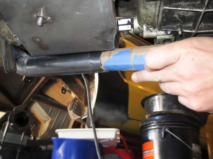
The next challenge was making a smooth merger for the 2 to 1 exhaust pipe transition. I was certain I only wanted one muffler on my bike. This is a much more difficult exhaust to build then one with two matching independent mufflers, but is lighter and more refined. I also hope that the exhaust pulses will smooth out the sound and cancel out some of the noise.  To make the y-pipe merger I used a template made from a cut up cardboard tube.  I slit the tube and made it the same diameter as the 1.5″ pipe with some tape. Then I notched the cardboard (much easier to work in paper then metal) to fit at the precise angle I wanted.

Make a Y pipe exhaust notching tubing   smoothly merging exhaust pipes

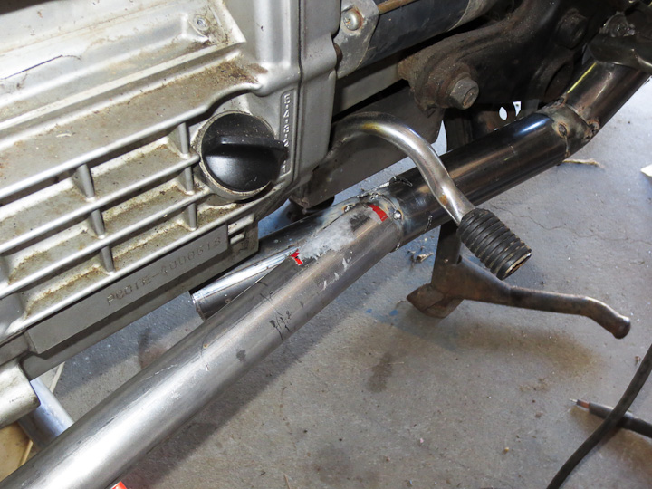
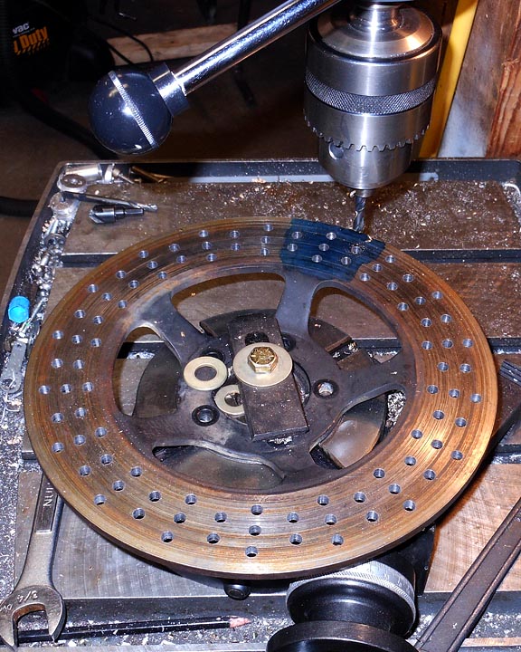
After transferring the pattern to the steel tubing I easily cut a clean notch out.  I spot welded the tube  in place on the bike to make sure I had the precise location, fit and angle.  I used a hole saw matching the inner diameter of the tubing and a hand drill to cut out the notch slug from the tube the notched stubb of tube was welded onto.  This is an easy way to make the second notch in the tubing.

make a y-pipe exhaust collector

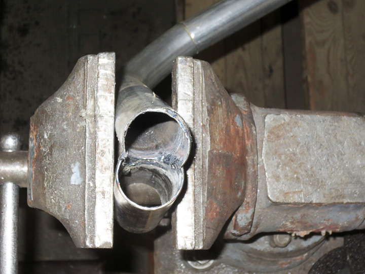
When making custom exhaust mergers, take the time to go in after fully welding and clean up the inside of the pipe with a carbide burr.   You are taking all of the time to build a custom exhaust for your ride so spend the extra few minutes to clean up the insides of transitions.  If you have ever done any fluid flow analysis and modeling at a merger you would understand how much a little time spent smoothing the inside aids in maintaining a nice laminar flow as the two streams mix.

cafe racer exhuast progress

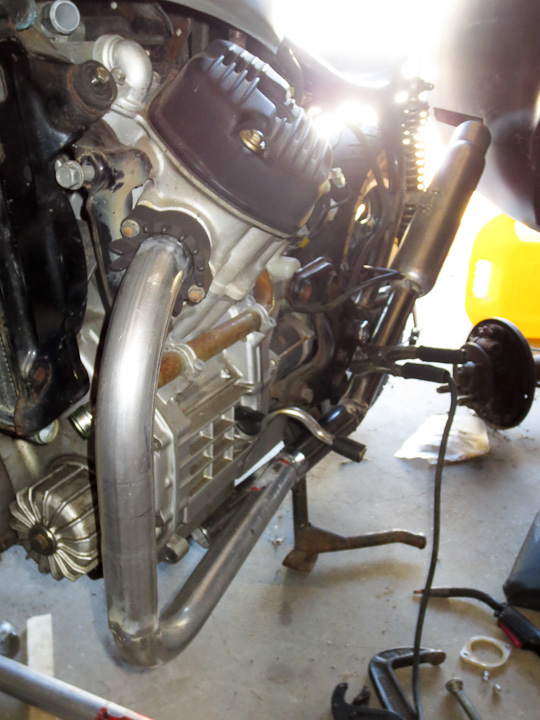
The fully welded merger in place, the last step is to fit some pipe between the other cylinder and the merger. Pretty straight forward.

custom cafe racer exhaust

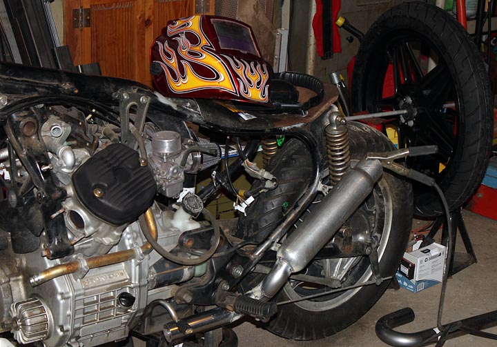
That finishes up the exhaust build.  I still need to finish all the welding at the joints and then clean it up in this photo.  I realize this is not a symetrical design. If I cared a bit more I may have gone through the trouble of turning both exhausts in and under the center of the bike making a more equal length flow path for the gases and a more symmetrical look on the bike.  I think I’ll leave that for the next bike I build.  I plan on building a bolt in baffle on the exit of the muffler should the noise level be louder then I want it to be.

CX-500 Cafe racer exhaust 02

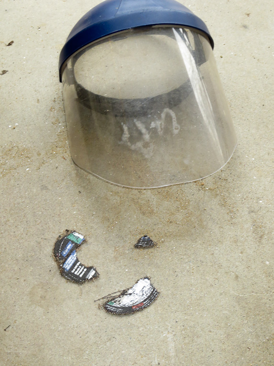
A final note about project and shop safety.  I’m often asked what tool I consider to be the most dangerous in my shop. I typically respond: right angle grinders. I have 4 of them in different sizes. One always fitted with a knotted wire wheel for cleaning joints up just prior to welding.  I’ve had more scary incidents with right angle grinders then any other tool, for example a cutting wheel explodes.  I always use a face shield when using a right angle grinders and you should too! Sure safety glasses are going to protect your eyes, but a full face shield is mandatory in my shop when using grinders.  The cutting wheel in the picture below bounced of the face shield with quite a bit of force while I was trimming the stubb of tubing I welded on making the y connector in this project.  I’d hate to have pulled bits of cutting wheel out of my face had I not been wearing the full face shield.

shattered cutting wheel safety


How to CNC machine a part from start to finish

Several readers have asked me for a post explaining the entire part creation process starting with a part concept, going through fabrication and ending with the part in use.   I use a ZAY7045 (RF45 clone)   Milling machine that I converted to CNC  to make parts for my projects.  In this post I will be sharing the details on the CAD design of parts, CNC coding, and fabrication process.   I will be using a two different pieces ( a headlight mounting bracket  and a speedometer mounting bracket) I made recently for my Honda CX500 Cafe Racer build to illustrate and outline the basic process of CNC fabrication of custom components.   I will keep the details simple such that everyone can understand how the CNC fabrication process works.

Speedometer mounting on a CX500 Cafe Racer

All parts start with a need,  in the photo above,  I need a bracket to locate and mount a single gauge to the upper triple clamp on my Cafe Racer Motorcycle Project.   I start by holding the speedometer gauge in place and taking some measurements.  It’s critical to carefully measure details like mounting bolt hole spacing.   As a rule of thumb I measure the smaller and larger dimension and take the midpoint between those numbers.    Here’s a Zac Shop Tip:  if you measure and calculate 138.43 mm,  it is very likely the actual value is the next nearest whole or half number,  ie. 138.5mm. After writing down the measured values on a small notepad, I next go to the computer to draw up the part.

Cad drawing of cnc machined part with different layers for different operations

After careful measurement, it is time to draw up your part in a CAD software package.  I’m quite fond of Dassault Systems, Draftsight software for generating simple DXF and DWG drawing files.  I am familiar and proficient with Solidworks, a 3d design software package which makes using the free Draftsight .dwg/.dxf CAD software an easy experience.  The above screen shot shows my version 2.0 headlight mounting bracket as drawn in draftsight.  You can see the part layer in white, the cutting layer in magenta, and the milling layer in green.  I manually set cutter offset in my drawings (a topic for another more technical post).  Each layer will have a different code generation step in the next part of the process.  Separating them out here makes life easier later on when generating the G-code for the CNC Milling Machine.

The CNC code generation software I use is not great, but I can not afford very expensive enterprise level software for this stage and thus I make do with what I have available.  I use this software to put the basic building blocks of the code in place.  I then rearrange, and edit the Gcode (CNC Machining programming language) into a form that is more usable and efficient.  The above photo shows a screen shot of the step in the process where I can set individual layer settings for the cutter.  You may recall I explained the need to generate separate layers earlier in the post and this is the purpose.  If you do not separate operations into layers you end up having to do a lot of tedious manual editing of your CNC Gcode program.

CNC Gcode generation

After chaining the layers together, so that the machine can generate code that does an entire loop in one go vs each individual drawing item  one at a time,  the software generates a basic G-code program.  I then carefully reorganize, and edit the code to make the program safe, do what I want, and in most cases more efficient.  The software tends to break things down such that the machine spends a lot of time traveling between points of entry into the material.  I reorganize the code snippets to minimize this which in turns shortens the machining time considerably.

The above photo, is the Gcode generation for the v1.0 headlight mounting bracket.  I made this first part as a fast test of the mounting location and strength of the 1/4″ thick 6061 aluminum plate I would be making this part from.  I will use this part in the next couple pictures vs the V2.0 headlight mounting bracket we’ve seen in the post so far.  I did not plan to put this post together ahead of time and missed some pics in the process with the v2.0 mount.   Rather then wait till I build the next part, I wanted to get this up to help my readers understand the process as soon as possible.

CNC machine software controlling the milling of a part   

Above you see a screen shot of the CNC machine control software running the machining process.  After lots of careful checking and setting a zero point on a larger piece of metal “stock” clamped into the machine I start the program and the machine does the rest.   This is really fantastic when you are making 4 of one part as after the first time the code has run through and is validated I will start the program and leave to do other tasks in the shop.  My CNC machine is not 100% self sufficient yet, so I periodically monitor it when it runs.  The number one problem with my current set up is coolant spraying everywhere making a real mess.  I plan to place the machine in a full enclosure at some future time.

CX500 cafe racer headlight mount Ver 1.0

The above photo shows the cafe racer headlight mount version 1.0 in place on the bike.   While this was a functional part, I learned I needed three changes for version 2.0.  The first change is that version 2.0  needed to be less ugly.  Aesthetics are important on some projects, and my Cafe Racer is to  be a thing of beauty.   Secondly I learned that I wanted to raise the headlight another inch or so in version 2.0.  Third I needed a slot to keep the headlamp from rotating, especially important to prevent it rotating with riding vibrations over time.

    CX500 Cafe Racer custom CNC fabrication

Above you can see the version 1.0 and version 2.0 parts together.  Clearly version 2.0 is superior in every way.

Custom CNC cafe racer parts built to orderAbove is the finished and painted bracket with the headlight mounted on the bike.   I am quite happy with the way it came out in the end.

     CX 500 cafe racer CNC fabrication

Similar to the headlight mounting bracket, I generated the code for the gauge mounting bracket for the speedometer.  This program required considerably more reorganization of the code to make run efficiently.  I use a simulation to determine the program run time.  The “as generated”  Gcode had a run time of almost 45 minutes.  I managed to get that down to 28 minutes by manually editing and reorganizing the G-code in the program.

CX500 Cafe Racer parts made to order   

Now for a bit on post CNC machine processing of parts.   I start by deburring all of the edges with either a deburring tool, a fine file, or sandpaper.   The machining process often leaves razor sharp burrs on the edges where it cuts the metal. The  parts used as examples in this post were primarily deburred with sandpaper.  I then wash them with warm soapy water to remove any cutting oils and coolant left on the part.  A quick trip to the sandblasting cabinet and they are left with a fine surface finish ready for paint.  Another trip to the shop sink to wash off any residue sand from the blast cabinet and they are ready for painting.

I often paint small parts like these brackets hanging from bits of bent copper wire through a bolt hole.    Several light coats of a quality paint results in a hard durable finish.  A hairdrier (buy one especially for this purpose, do not “borrow” your significant others for painting car parts) can be used to help flash dry the paint between coats, or in the winter time cure the paint quickly in colder temperatures.

Cafe racer guage mount speedometer

Here’s the finished CNC machined bracket on the bike.

Cafe Racer Speedometer  CX500

    I am very happy with the way these parts came out and the overall look on the bike as this project progresses.  If you want more information on these parts (drawings, etc)  or would like me to make one of these parts for your CX500 motorcycle project,  leave a comment on this post or email me at zac at projectsbyzac.com.  I hope this helps my readers understand the process of how to make parts with a CNC machine.  When I finish my 3d printer project I will do a similar post on 3d printing parts from start to finish.

I’ve gotten a number of requests for the drawings I used to make these parts. Here are the DXF files I used to mill each of these brackets, this was before I had real cam software so they are ofset by 0.125 for G-Code generation via very primitive software.   I had to convert the DXF to PDFs to share them with you in wordpress.  It claims DXF is a security risk.  You can convert back or open them in your cad software and everything should still be ok.  CX500 front light mount   &    cx500 guage mount

Building a Cafe Racer Custom Exhaust – Part 1

Building a cafe racer custom exhaust system

I started in on the exhaust system for my CX-500  Cafe Racer project.   I started with the rear of the exhaust for the CX500 Cafe Racer, placing the muffler exactly where I wanted it to be on the bike as the first step.  This build was going to be a 2 into 1 style motorcycle exhaust,  with only one muffler for a  cleaner and cooler look.   Investigating hundreds of photos and parts catalogs I could not find exactly what I wanted for a muffler. I did not want anything chrome, megaphone or cone style mufflers, or anything flash in general.   I wanted something vintage,  flat black, and a little bit crude to go with the Cafe Racer style.  I ended up buying some mandrel bent tubing, and a bare muffler core to fabricate a custom exhaust.  I’ve done a lot of custom exhaust builds over the years, check out an earlier post where I show an exhaust build on a Ferrari 308   from last summer.

Custom Cafe Racer Exhaust system parts

Here are the parts needed to build the custom exhaust system for my cafe racer CX500 motorcycle exhaust.  I ordered up two 1.5″ diameter  U bends (PN: SCH-015016U) ,  two 1.75″ diameter J Bends (PN: SCH-017516J),  & a 12″ muffler core (PN: JEX-A3012B)   from Summit Racing.   Summit Racing is a great cheap place to buy exhaust tubing and mufflers.  They have been my go to auto parts supplier since high school.   I have a fairly large selection of nominal auto exhaust tubing in stock from previous projects but nothing in the motorcycle size range so I ordered everything needed to build the Cafe Racer Exhaust.  The tip on the muffler core I fabricated from some 2.5″ tubing and I will put an internal removable baffle into it to help quiet the exhaust some.  I am certain that  just the core it will be louder then  I want for regular daily riding.

Cafe Racer Exhaust build  muffler mounting    

Mounting the muffler was trickier then I anticipated. I had my CNC Milling Machine  bang out a variety of different mounting brackets for this project.  I ended up using several of the smallest of the three sizes I made and one of the larger skeletonized mounting tabs to put the muffler on the bike.   In the above pictures you can see where I located the muffler on the bike.  I am pretty happy with where it is mounted.

custom motorcycle exhaust build for cafe racer CX500

The exhaust tubing runs inboard and under the lower motor/frame mounting. This is important as I plan to lower the foot pegs a bit and make a new foot shift lever for the bike.  I find with the new seat and the low forward clubman handlebars that it is a bit uncomfortable with the stock foot pegs on the bike.

In the next post on the cafe racer custom exhaust system build,  I show how I make the 2 primary pipes merge into this rear exhaust system.

Mounting and Balancing a CX500 motorcycle tire

Bonus Photo:  The mounted and balanced new front tire on the painted wheel.  I will paint the wheel weights black before mounting them permanently with double sided tape.

Honda CX500 Cafe Racer Build Progress

Drilling the rotor Honda CX500 Cafe Racer build

Just a quick progress report on the CX 500 Cafe Racer Build project,   I’ve cross drilled the rotor using a rotary table.  This was surprisingly quick once I dialed in the rotor to the rotary table eliminating any run out.  It went so well that I suspect I will be cross drilling lots of rotors in the future.

Painting a motorcycle wheel tips

I stripped, sanded, and painted the front rim with some quality satin black wheel paint and it looks awesome.   I used a large plastic tub that fit the wheel and wet sanded the entire thing by hand.  Sandblasting would have been considerably easier but my blast cabinet is not large enough.  Sanding all of the backside and the nooks took forever.  Next time I would pay to have it blasted at a shop.  It came out looking awesome though and I can’t wait to see the now completed front end reassembled on the bike.

Cafe racer handlebar controls 3d Model

You have to use your imagination a little bit for the above image, but this is the 3d model of the handle bar switches I will use on the bike in place of the stock ones.  I will have the CNC machine bang out two of these.   They can each house 2 switches or buttons. I ordered the right size cutter some time ago to make these and plan to get them machined in the coming week.  The wires will run through the handlebars and it will be a nice clean installation.

Battery box for CX500 Cafe Racer Build

Above is the battery box on the bike.   I built this to relocate and clean up the install of the battery and starter solenoid on the bike.  I’d like to get a mini ATO fuse block that mounts through the side of  this as well.  I will sandblast and paint the box satin black, even though it’s made from 316 SS.  Here’s a pattern if you want cut and fold a battery box of your own for the CX500:  battery box Sheet metal pattern for Honda cx500 cafe racer build

CX500 Starter solenoid inside battery box    

You can see the battery and solenoid fitment in the belly box.  Sadly it warped a bit when I welded it up. I did not take my time and regret it.  I’ve hammered it back a bit and used the press to get it to fit comfortably in place.  You can not tell on the bike but seeing it from the top like this it is apparent that it is a bit skewed.   I will make a bolt in hold down strap for the battery and this bit of custom fabrication will be 100% done.   I will need to address the wiring as well in the reassembly stage which I am fast approaching.

That’s all for now, more soon as I want to get this project finished and out the door ASAP.