This post continues from an early post, antibacklash ballscrew upgrade on RF45 ZAY7045 Milling machine – Part 1. After mounting the anti-backlash ballscrew and assuring that it was as square to the table travel as I could get it, I worked on installing the end plates and then the captive support bearings a single 5202 and a single 6202 sealed Nachi bearing.
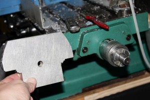
I cut out rough profiles of the endplates on the band saw from some 3/4″ 6061 aluminum stock I had on hand. I used the original endplates as rough guides. I did not machine the outer profile very carefully as I felt it was not important enough to justify the time. I rough drilled the center hole, then marked the actual center by tracing the leadscrew. A large endmill centered over the markings bored out the ballscrew opening. This easily lined up the screw in the hole through the support piece. I liked the idea of using dowel pins to maintain a fixed alignment of the end plates. Transferring the dowel pins from the original plates worked poorly so I drilled and reamed new ones with over under reamers.
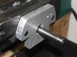
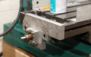
After mounting both end plates I focused on the stepper driven side as it would support the leadscrew in both an axial and radial fashion by using a 5202 double row angular contact bearing. This end is critical as the 5202 bearing is designed to take the axial thrust loads during the operation of the cnc milling machine resulting in no backlash when changing directions. I needed to machine a spacer for the 15 x 1.0mm bearing nut to tighten my anti-backlash ballscrew onto the 5202 bearing. I also machined the bearing retention block. This is just a 3/4″ thick aluminum square faced and bored to accept the 5202 bearing with 10-15 thousandths of the bearing sticking out. The bore is machined 10 to 15 thousandths shallow so that when tightened down against the end plate the bearing will be held captive with no play in the axial direction. Drilling and taping the bearing retaining block in place was done very carefully by clamping down the table, tightening the bearing hard against the end plate by turning the leadscrew, and carefully transferring, drilling, and tapping the 6mm threaded holes. This way I was able to use the leadscrew to provide proper alignment of the bearing support block. It required some careful hand work, but worked well in the end.
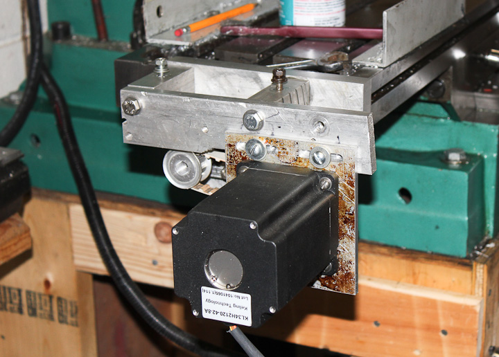
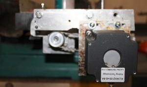
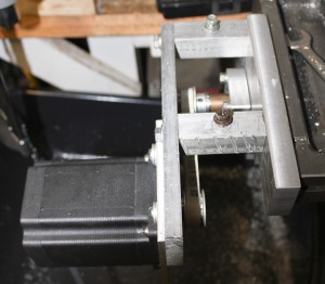
As this is CNC machine version 2.0 I decided to reuse much of my original mounting mechanism for the motor. Originally I had relied on a clamp on mount from the original x axis drive that came with the ZAY7045 mill drill from lathemaster.com. Version 2.0 would mount off of the end plate allowing me to sell the x axis drive motor and clear up much needed shelf space in the shop . I am using L series timing belts tensioned by a slotted slide mechanism. Another change from version 1.2 include a reduction in pulley ratio from 1:2 to 1:1 using 10 tooth L series timing pulleys (part number A 6A 4-10DF05016) from Stock Drive Products/Sterling Instrument allowing for much higher rapid traverse speeds. I did have to open up the bore on the pulley to 15mm from the 0.500″ inch stock bore.
With this new ball screw the machine can move the x axis at speeds in the 30 ipm range as an upper limit. The earlier version had a max travel speed of only 8 IPM. Mostly due to the motors not being able to drive the poor quality inefficient ACME leadscrew. I plan to alter my motor configuration in the future to a direct drive set up with the motor coupled to the ballscrew via a zero backlash misalignment bushing.
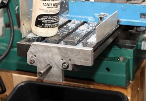
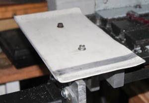
The last addition to the drive mechanism is a splash shield. I use a flood coolant system for CNC milling, making a splash shield for the drive mechanism a must. I bent and hammered out some 0.095″ Al sheet I had handy such that all of the edges are raised except where it floods back into the milling machine table resevoir.
My work is not done on this project but this post is for now. I carefully measured the other end of the antibacklash ballscrew. I need to have the 15mm diameter bearing area of the screw (upper right photo at the end of the screw) extended to a length 77mm from this end of the ballscrew. This is required to mount the other support bearing (6202) and the bearing retainer onto the end plate. This side only supports the ballscrew in the radial direction and is less critical. I plan to leave the 15mm dia section long so I can later add either a rotary encoder and/or a manual control handle. In order to machine the leadscrew end I need to dissassemble the entire machine yet again, carefully remove the ball nut, and find someone with a lathe who is kind enough to help me out turning it down carefully. Sadly, my 100 year old lathe is not up to the level of concentrically I need machined.
I have driven and tested this new ballscrew setup and it is vastly superior to the original ACME leadscrew. Higher speeds will allow for faster machining times, especially on parts that have many non cutting rapid moves, such as drilling bolt patterns. I realize now that I should have replaced the leadscrews years ago and that I now must do the Y axis. Likely I will measure and get started on the Y axis upgrade when I disassemble and have the x axis anti-backlash ballscrew end machined. I hope my work helps someone with their own conversion. I looked hard to find details on what screw would fit, where to buy one, etc. without much success.
Very good work, I am in the process of trying to convert a new ENCO RF-45 and I really
appreciate you providing links to the parts you used. I like the idea of the Pully system for driving the x,y,z and had searched for a supplier for gears without much
success. You had a great link for such a supplier.. Awesome
Thanks again John
John, I’m glad you found my post useful. Good luck with your conversion!
Zac,
What sort of backlash do you measure on your converted axis now that you have the ballscrew?
The backlash is about 1.5 thousandths of an inch now with the ball screw. My timing belt is under a good bit of tension so I am pretty confident that’s all in the screw/nut assembly
thank you for the information. I have a Harbor freight version of a round column mill which I am converting. In looking at ball screws, the Chinese have a huge number of suppliers on ebay at very good prices for C7 ball screws which I assume yours is. at least two said they will machine the ends to your specification for very little money. C7 is a rolled ball screw so is inferior to a ground C5 or better but the price is half or less of the ground version and on my machine the slop in the parts makes the better screw worthless. The slop in the system as designed is mostly in the horrible design for the thrust bearings which is more of a joke than a bearing to reduce play. I notice a whole lot of other machines have the same problem. What I did to fix it for a while was to get a m17x1mm die from china, a nut from a supplier on amazon and threaded the thrust bearing end. Put a thin spacer on the end of the acme screw,it was not machined at ninety degrees to the shaft, assembled it back together with three wave washers, 11/16 as 17mm is impossible to find, the M17 nut,a clamp fitting, 68 dollars for a locking nut was a bit much, machined off the handle end to fit, put another M17 to tighten the whole assemble, tightened up the clamp and the slop was gone. As you point out that does not fix the high wear on the nut by the screw so will be converting to ball screw. this temporary fix actually cost less that fifty dollars so saves some money for other things. You do the same for both axis for that cost