A quick easy way to make an XL series timing belt mount

XL timing belt mount

Timing belts are useful for all sorts of synchronous motion.  They can be used to connect a rotary encoder to a lathe spindle or to provide linear positioning on a 3D printer.  They have little stretch or flex and can accurately transmit rotational motion.   One of the challenges with using timing belts is mounting them in your projects.  This is especially true when you want to use timing belts to convert rotational motion of a computer controlled stepper motor into positionally accurate linear motion on a project like my 3D printer build.  Here’s a fast and easy way to make yourself a timing belt clamp and mount for your project.  The clamp shown in this post will function as the y axis mount on my DIY 3D printer (photo installed at the end).

how to make a timing belt clamp using hot glue-1645

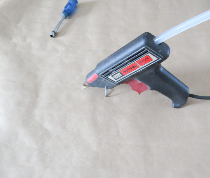
Any craftsman, maker, car guy, or project loving person knows about and owns a hot melt glue gun. They are good for many things,  in this project the hot melt gun is going to provide the plastic uses to pattern our timing belt interlock features on a substrate.

how to make a timing belt clamp using hot glue-1648    L series timing belt clamp

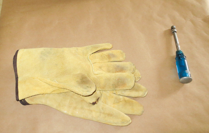
Wear gloves when playing with hot things!

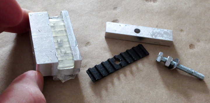
First you need to make a mounting block for use as a substrate from your material of choice.  Aluminum in this case.  I machined the part to fit onto my 3D printer’s y-axis structural cross member.  I cut a small scrap of XL series timing belt to fit the groove. This is why it is always good to hold onto things like a scrap bit of timing belt.  It may be hard to see in the picture above but I drilled a series of 6 shallow holes into the timing belt slot to allow the molten hot glue to seep in and form mechanical interlocks.  It’s best not to rely on the adhesive strength of the hot glue, mechanical interlocking features for the polymer to mold into provide good shear resistance.

Pre-heat the substrate.  You could use a project toaster oven,  heat gun, 500w lamp, etc.  I used the woodstove.  If you try this with a cold substrate the hot glue will cool too quickly to mold to the features of the timing belt. You want the substrate warm so it does not pull heat out of the molten polymer before we can mold it to the timing belt.

XL series timing belt mount using hot glue - 7

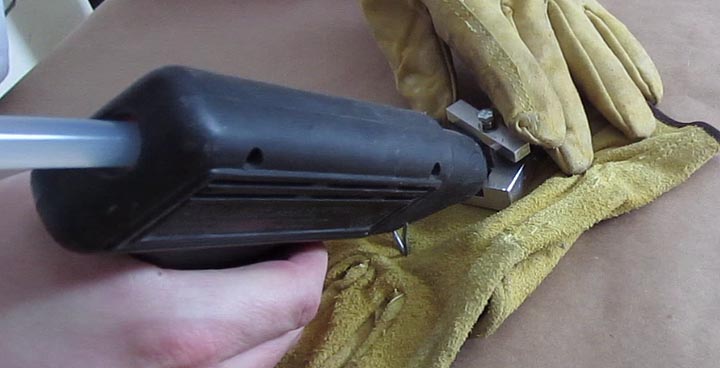
Quickly take your preheated substrate from your heat source, put it on a nonflamable surface (leather glove in this case) and fill both sides with hot glue quickly.  Use a bit more then you think you need, it will seep out the ends if there is too much in the slot.

XL series timing belt mount using hot glue4

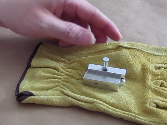
Then clamp down the timing belt into the molten plastic with the screw. I used a long screw to provide alignment and a nut to make clamping  easier and faster.  It is also acceptable to just squish it down with your fingers.   Put the hot assembly into cold water to quickly cool the hot melted plastic before it can seep out of the cavity.

XL series timing belt mount using hot glue

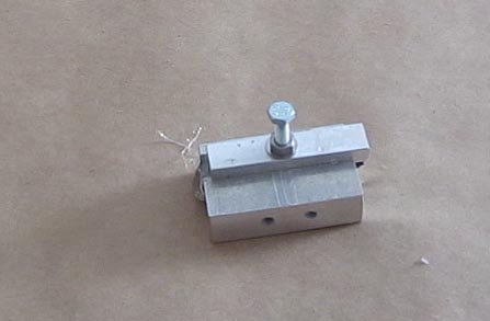
Let it cool completely before disassemble.  I’ve never had any issue with the hot glue sticking to the timing belt enough to be a problem.  Usually it is possible to remove the Timing Belt used to mold the plastic with fingers. If it is a bit stubborn in coming free use a small pair of pliers to get a grip on the bit of timing belt and slowly pull it up and away.

XL timing belt mount

When disassembled, trim up any of the plastic that seeped out with a sharp exacto knife or chisel.   As you can see you get a perfectly molded Timing Belt clamp that can be used for your project.

XL series timing belt mount

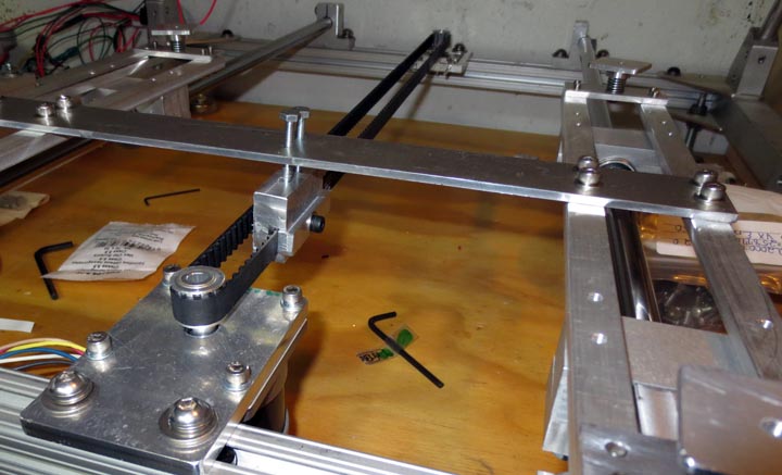
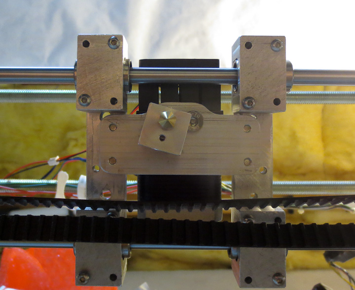
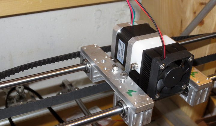
Here’s the finish timing belt in place on the 3D printer project.  The stepper motors have 10 tooth pulleys on them to drive the XL series timing belts allowing the y axis to move with positional accuracy.  More on the 3d printer progress as I have time to write.  It is nearly operational!


Converting a wood bandsaw into a metal cutting bandsaw

bandsaw conversion metal cutting

I needed a small metal cutting bandsaw for pre-cutting stock for my 3 axis CNC milling machine but I did not want to spend a lot of money on a new one.  I had been checking craigslist when this little gem came along.  It’s a Rockwell/delta 10″ bandsaw (here’s a copy of the owners manual for this saw) that  takes a 71 3/4″ blade.  It has a nice rigid cast iron frame, metal band wheels, and an open drive mechanism making it perfect for a conversion.   The major difference, outside of the blade itself, between a wood cutting bandsaw and a metal cutting bandsaw is the blade speed.   Wood cutting bandsaws run too fast for metal cutting.  To convert over to metal cutting duties I needed to reduce the speed of the band wheel by about a factor of ten.

bandsaw conversion- gear reducer   Band saw conversion metal cutting

My initial inclination was to use a larger pulley to slow down the blade but some calculations determined even a double pulley reduction would not slow it down as much as I would like.   I went through my list of parts on hand and decided to employ an EPL series motion control gear reduction unit with an 8:1 reduction ration.  That would slow the bandsaw blade down with the pulleys I had on hand to a good speed for cutting metal.

Making a spindle- metal cutting bandsaw conversion    metal cutting bandsaw

The gear reduction drive is designed to bolt onto a face mounted motor and as such has a female shaft mount on one end.  I quickly turned a spindle from some steel stock to 24mm on the gear drive end and 5/8″ on the other for the pulley.  The goal of this project was to quickly have a good metal cutting bandsaw with what I had on hand and minimal spend.   Coming back to the discourse on design, I was designing with what I had available for this project.  It may seem a bit ridiculous to use such an expensive part on a $50 saw but I figure I can always pull the gear reducer later if a more pressing need for it arises.

 DIY metal cutting bandsaw   DIY metal cutting bandsaw conversion speed reduction

I decided to reuse the original belt that came with the saw.  I upgraded the stock pulley to the largest one I had on hand, and drilled some holes into the legs of the stand to mount the reduction drive.  The gear drive needed a bracket to support it on the other end.   One was fabricated out of 1/8″ steel stock.   This arrangement required the motor to be relocated which was accomplished by drilling 4 new holes in the correct location on the base of the stand.  Be sure to check the motor rotation and reverse it (usually swapping wires inside the motor wire box) to correct it if the blade is going the wrong way.

bandsaw conversion   how to convert a wood bandsaw to metal cutting

The new drive belt is a 4L290, as I happen to have 3 of them on hand.   I only had to buy 2 parts in addition to the bandsaw itself for this project.   The first was the small pulley that is mounted on shaft of the gear reduction drive.  I purchased a 2 3/4″ dia pulley with a 3/4″ bore at my local tractor supply store.  Tractor supply has a good selection of motors, pulleys, and belts in stock.  Not a lot of hardware stores carry these items in this day and age.   I had to bore out the pulley’s 3/4″ bore  to 20mm on the lathe to make it fit onto gear reduction unit output shaft.

Wiring on old tools is horrific and when I opened the electrical box up I was thankful I didn’t get electrocuted when I tested out the saw.  I replaced all of the 40 year old scary wiring and upgraded the switch with a modern unit.

Wood bandsaw to metal bandsaw conversion     Reducing the blade speed on a wood cutting bandsaw

The only other part I purchased for this project was a small spacer for the handybox that encloses the wiring for the bandsaw.  These are available at Home Depot for less then a buck.  The new switch I selected did not fit in the enclosure, requiring the spacer.  I used the CNC mill to cut the opening in the switchplate.

The finished tool works well and I’ve already cut several linear feet of aluminum stock on this saw, with a 6 tpi wood blade in place.  I’ll be ordering up some good bi-metal blades in the near future.  I am very happy with this little project and foresee myself getting many years of good use out of this saw.

What defines a robot? The Tin Can Robot build

Tin Can Robot walking

What defines a robot? Lately I have had many discussions with my nephew about robots.  He is going through a robot loving phase of his childhood.  We’ve spent countless hours on the phone talking about the CNC machine and 3D printer.  Both of these are “robots” in essence.  When he first saw pictures of the 3D printer his comment was, it did not look like a robot at all and therefore was not a robot.  We then had a lengthy discussion about what makes something as a robot.

Webster defines a robot as

  1.   a machine that looks like a human being and performs various complex acts (as walking or talking) of a human being; also : a similar but fictional machine whose lack of capacity for human emotions is often emphasize
  2. a device that automatically performs complicated often repetitive tasks
  3. a mechanism guided by automatic control
Hard to argue with those definitions. Which brings us to the project part of this post, the 4M Tin Can Robot by Toy Smith.  This little project was fun to build, but is it really a robot?  Does walking forward in a straight line make it a robot? We concluded that because it is a toy robot, it is indeed a robot  but it was not a real robot because it did not actually perform any task and was not controlled.  That being said, it is a great project for a young robot lover. My nephew built the Tin Can Robot Kit almost entirely by himself under some close Uncle Zac supervision.

Tin Can robot in the box

Above you see the Tin Can Robot in the box.  It comes in a rather large box considering what is inside.  The parts are packaged in small plastic bags and the instruction sheet in the box was easy to follow.  It does not come with the two AA batteries you need to have real robot action once it is assembled. Be sure to have them handy for the build so you can see the Tin Can Robot come to life upon completion.  If you want to purchase one of these great kits you can find them available here.

Tin Can Robot assembly Instruction

The assembly instructions for the Tin Can Robot are clearly illustrated (click on the above image for legible full size image if you lost your instructions or need to reference the Tin Can Robot instructions).  The only part I helped my nephew with directly was the insertion of the wires into small brass rivets with little plastic plugs.  It required a fair bit of force and my nephew was not capable of pushing the plastic plugs into the rivets.  There are a lot of small screws in this kit.  It’s best to open the parts bags over a tray or bin of some sort to keep them from getting lost on the floor.  Because the screws are small, my nephew was capable of screwing each one in with a small screwdriver on his own.

Tincan Robot action shot

The Tin Can Robot sits in a special place on a shelf proudly displayed by my nephew when not in use.  It was a great project for and both of us had lots of fun both building and playing with this toy robot kit.

Here’s a short video clip of the robot in action (sound affects added post production):

Assembly and evaluation of the QU-BD MBE 1.75mm Filament Extruder for 3D printers

3D printer head 1.75mm filament extruder

If you haven’t seen my earlier posts, I’m building a 3D printer, roughly modeled after the RepRap Prusa and RepRap Mendel designs but considerably larger.   In an earlier post I shared my own 3mm filament stepstruder plastic extruding 3D print head design and photos showing progress on its development.   While searching the interweb for nozzles to purchase, I came across the QU-BD website with 3D printer supplies.  Given the low cost (starting at $34, $63 all decked out with bullet heater and stepper motor) of this 3d printer extruder, one was ordered on the spot.  It was as received as you see in the above photo.  All of the parts were nicely segregated into plastic bags.

3D printer head by QU-BD

The first step was to tear into the packages and examine the parts.  The design is simple and well thought out.  It uses a combination of off the shelf components and custom machined pieces.  I really like the modified heat sink and small fan.  These two parts will also  be used on the 3mm filament print head of my own design as well.

3d Printer head assembly MBE v9

Assembly instructions are available on the QU-BD website here  or available on my site saved as a pdf here.  The above shows the body of the 1.75mm filament plastic stepstruder  on the NEMA 17 stepper motor that came with the kit.  Here is the data sheet for the Wantai 42BYGH610 stepper motor included in the QU-BD MBE V9 3d printer extruder kit.

3d printer head stepper extruder   d printer head stepper extruder

The kit assembled relatively easily.  All of the parts were well machined with the exception of the aluminum rectangular heater block.  The M6 threading was drilled and tapped at a slight angle (~5 degrees).  The result was that the nozzle did not sit flush against the block when tightened in place.  In the photo below you can see the misaligned angle of the heater block in relation to the body of the stepper motor and extruder.

3D printer head by QU-BD

I felt this minor issue was not worth the hassle of calling and complaining to QU-BD.  In fact given the price of the kit, and the DIY nature of product, issues like this are to be expected.  Some quick machining on the lathe squared the faces up to the M6 threaded through hole correcting the problem.

3D printer head by QU-BDA

The overall design of this 1.75mm filament stepper based extruder 3d print head is well thought out. The parts are all well made with the exception of the heater block.  The only piece that I felt was not useful in this kit was the included mounting plate.  This part will not  be used in my printer build but I suppose it is bolt in for some of the popular DIY 3D printer projects available in kit form.

3D printer head by QU-BD

In the above photo you can see my mounting plate. Because of the much shorter hot end/nozzle portion on this 1.75mm filament plastic stepstruder I needed to drop the entire head as close as possible to the linear shafts that make up the x axis on my 3d printer build.  I machined a 0.150″ drop into the mounting plate. This gets the nozzle down almost  well below the timing belt and linear bearing mounts.

3D printer head by QU-BD

Here is the QU-BD MBE v9 Extruder in place installed on my 3d printer.  It is small, looks good, and fits well with the rest of the machine.  As of now my printer has mounts for 2 different print heads.  Eventually I’ll settle on one or the other and machine new bearing supports (the aluminum rectangles with the green M’s on them) to reduce mass as much as possible.  Less mass means less inertia resulting in faster print head movement.  The plan is to redo the bearing mounts as well when it is fully operational.  They will be produced by printing them out in ABS, thus having the machine produce upgrade parts for itself.