Timing belts are useful for all sorts of synchronous motion. They can be used to connect a rotary encoder to a lathe spindle or to provide linear positioning on a 3D printer. They have little stretch or flex and can accurately transmit rotational motion. One of the challenges with using timing belts is mounting them in your projects. This is especially true when you want to use timing belts to convert rotational motion of a computer controlled stepper motor into positionally accurate linear motion on a project like my 3D printer build. Here’s a fast and easy way to make yourself a timing belt clamp and mount for your project. The clamp shown in this post will function as the y axis mount on my DIY 3D printer (photo installed at the end).
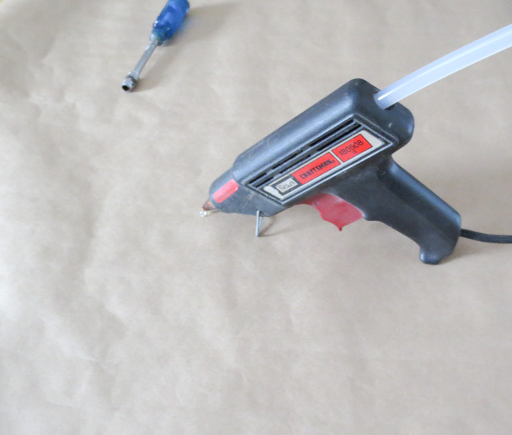
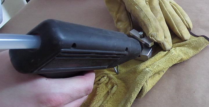
Any craftsman, maker, car guy, or project loving person knows about and owns a hot melt glue gun. They are good for many things, in this project the hot melt gun is going to provide the plastic uses to pattern our timing belt interlock features on a substrate.
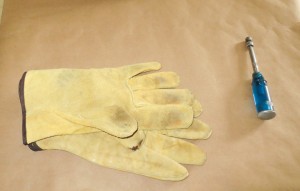
Wear gloves when playing with hot things!
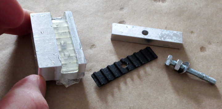
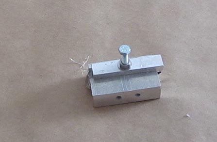
First you need to make a mounting block for use as a substrate from your material of choice. Aluminum in this case. I machined the part to fit onto my 3D printer’s y-axis structural cross member. I cut a small scrap of XL series timing belt to fit the groove. This is why it is always good to hold onto things like a scrap bit of timing belt. It may be hard to see in the picture above but I drilled a series of 6 shallow holes into the timing belt slot to allow the molten hot glue to seep in and form mechanical interlocks. It’s best not to rely on the adhesive strength of the hot glue, mechanical interlocking features for the polymer to mold into provide good shear resistance.
Pre-heat the substrate. You could use a project toaster oven, heat gun, 500w lamp, etc. I used the woodstove. If you try this with a cold substrate the hot glue will cool too quickly to mold to the features of the timing belt. You want the substrate warm so it does not pull heat out of the molten polymer before we can mold it to the timing belt.
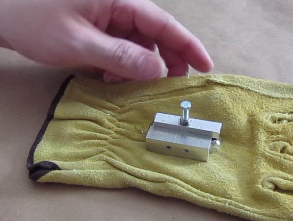
Quickly take your preheated substrate from your heat source, put it on a nonflamable surface (leather glove in this case) and fill both sides with hot glue quickly. Use a bit more then you think you need, it will seep out the ends if there is too much in the slot.
Then clamp down the timing belt into the molten plastic with the screw. I used a long screw to provide alignment and a nut to make clamping easier and faster. It is also acceptable to just squish it down with your fingers. Put the hot assembly into cold water to quickly cool the hot melted plastic before it can seep out of the cavity.
Let it cool completely before disassemble. I’ve never had any issue with the hot glue sticking to the timing belt enough to be a problem. Usually it is possible to remove the Timing Belt used to mold the plastic with fingers. If it is a bit stubborn in coming free use a small pair of pliers to get a grip on the bit of timing belt and slowly pull it up and away.
When disassembled, trim up any of the plastic that seeped out with a sharp exacto knife or chisel. As you can see you get a perfectly molded Timing Belt clamp that can be used for your project.
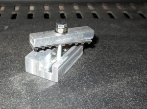
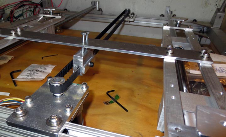
Here’s the finish timing belt in place on the 3D printer project. The stepper motors have 10 tooth pulleys on them to drive the XL series timing belts allowing the y axis to move with positional accuracy. More on the 3d printer progress as I have time to write. It is nearly operational!
Hay, Nice work. I just had one question though. Where did you purchase your timing belt and for approximately how much money.
Chris, I purchased the timing belt from Stock Drive Products/Sterling instruments. Here’s the link: http://www.sdp-si.com/