A Simple Cherry End Table

Simple to make Cherry End Table

I love working with wood and have been working with it since elementary school. I almost always have one or two woodworking projects going for those days when I want to sequester myself from life for a few hours in the shop.  However, I can’t remember the last time I built a piece of furniture for myself.   Usually I’m building something for a family member or friend, and occasionally a stranger who saw my wood craft or was referred from a past customer.  This project is for myself and will see daily use.

Simple to make Cherry End Table

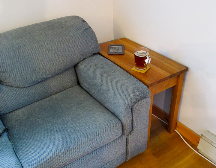
The last time my brother in law visited I had him help me move a couch into my office.  After putting the couch in place I was left with a very odd space that quickly accumulated clutter.  I enjoy reading on the couch and use it when I video conference as well.  A clutter spot was not acceptable.  I took some measurements and quickly drew up a simple design for an end table to fill the space.  I settled on a style that roughly falls between shaker and american country.  Practical, simple and built Zac tough.  Know yourself as they say, inevitably at some moment in the future this table will either end up as a bench or step stool.  With this table’s mortise and tenon construction and thicker boards, it will be up to the task of supporting my large mass.

Simple to make Cherry End Table

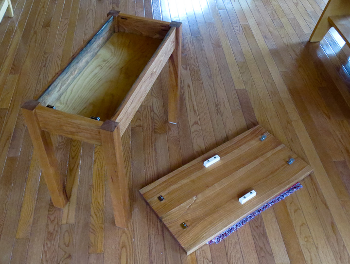
When designing the table, I originally included a shaker style drawer.  When I started cutting the wood, I realized how small and useless the drawer would be in terms of storage.  With small tables, the space needed for the drawer itself results in a loss of a large percentage of the available storage space.  I decided I would go with a flip up top.   However, with a lack of readily available hinges with the correct overlay, I changed to a lift off design.  This way I maximized the storage space for my seldom used electronic wires and other small items.

How to make a cherry end table -2216    How to make a cherry end table -2220

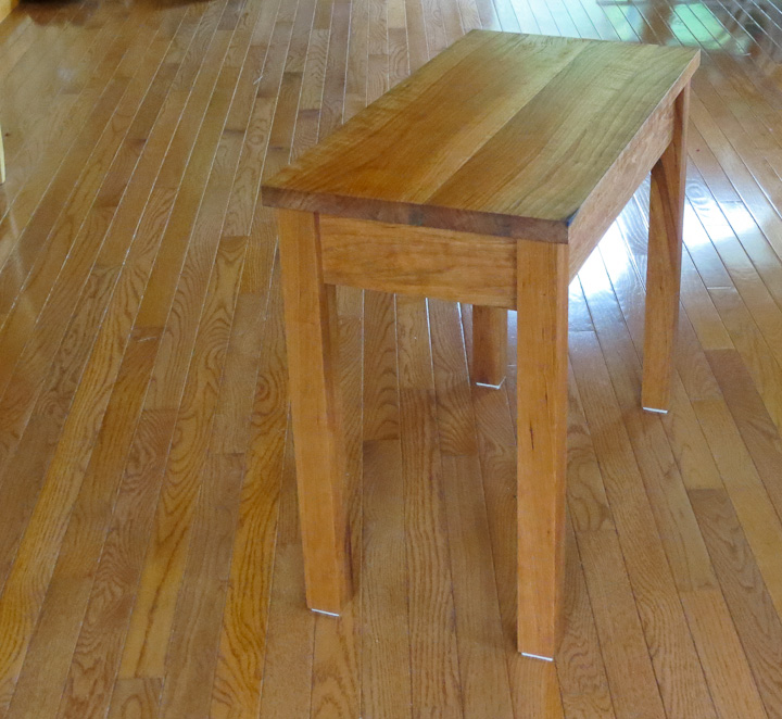
I chose a simple Danish Oil Finish for this table.  I like oil finishes. They are easy to apply and typically bring out the beauty of the wood grain.  If you get a ding or scratch they are easy to repair by simply re-applying more of the oil.  As this table will see tough daily use, in a few weeks when the oil has fully dried,  I will take the top and put a few thin coats of a durable polyurethane to seal the top.

How to make a cherry end table -2189   How to make a cherry end table -2187

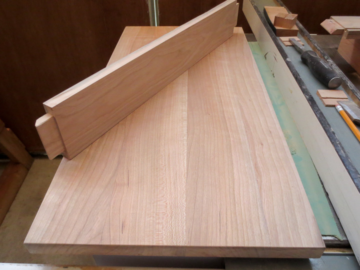
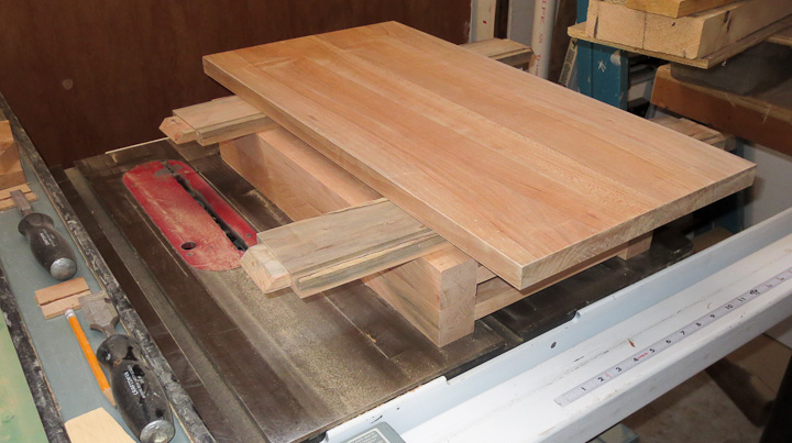
Not much to a small table like this,  you can see the entire table stacked up on the saw prior to assembly in the above right photo.

How to make a cherry end table -2192    How to make a cherry end table -2191

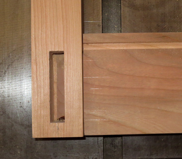
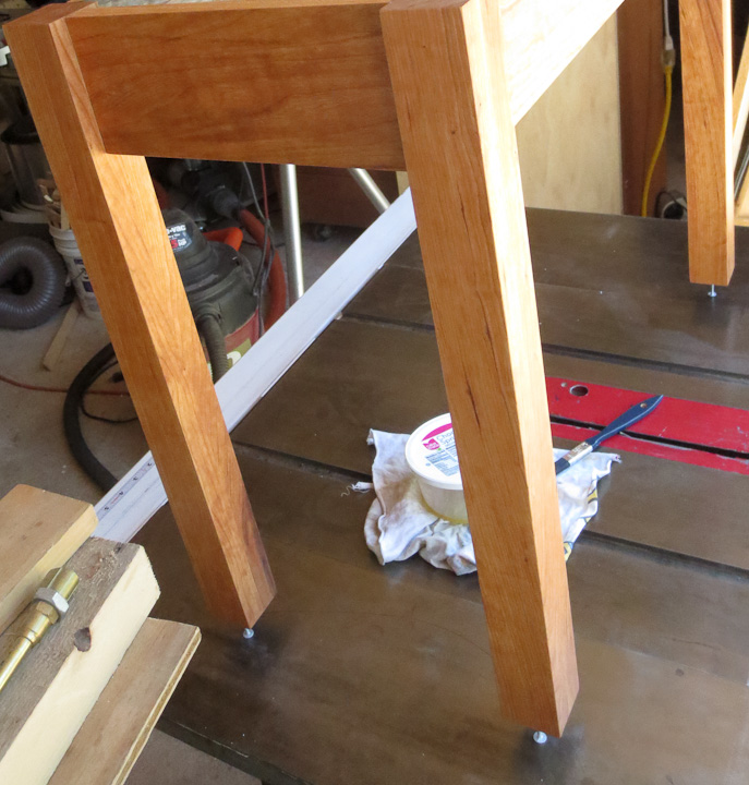
Some shots showing the details of the mortise and tenon work on the table.

How to make a cherry end table -2212     How to make a cherry end table -2211

Here’s a useful tip.  When finishing table and chair legs.  Drill a small shallow hole just undersize of a roofing nail.  That way you can stand the project off with a roofing nail to allow prevent it from picking up any grit while the finish is drying.   With oil finishes I also like to let the end grain soak up oil by resting it in a plastic tub full of the oil finish.  End grain can soak up a lot of finish and this ensures it will be well sealed.

How to make a cherry end table -2209

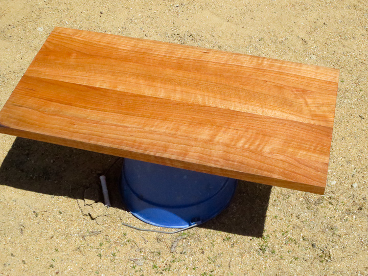
Cherry is a beautiful wood.  Left au naturale  cherry shows off a beautiful grain and color of the wood.   Cherry darkens with time nicely but I enjoy the lighter feel of the natural wood when it is new. In a year this will be twice as dark.  Part of the joy of Cherry is the gradual color change as the wood oxidizes.  All to often people are quick to stain cherry dark.

In closing, I built this table almost entirely from wood I milled from a short cherry long my friends father had cut when we lived near each other as kids.  He had this log in the garage for all these years.  Late last summer he clearcut some trees and let me come snag a log to turn into lumber.  In addition he gave me the cherry log he had kept in the garage.  While the log was badly checked with cracks, I was able to get some usable wood and build this small project from it.  Thanks Mr. Field for the log!  This is what I did with the lumber I cut from it.

Low cost PID control box for heating/cooling

Assembling a PID temperature control box-1795

One of the joys of the modern world is the availability of low cost PID temperature control modules.  These have been around for a long time in the industrial world but in the past were cost prohibitive for home hobby use.   Now you can buy a pid temperature controller for $25 from Amazon.com.   Adding  in a type K thermo couple ($6),  a 25A SSR ($7) , and some items from your parts bin (switch, outlet, plug, fuse holder) you can build a nice little temperature control panel capable of keeping a piece of production equipment at a fixed temperature while running for less then $50.

Assembling a PID temperature control box-1793   Assembling a PID temperature control box-1792

Only basic instructions are included with the controller, if you aren’t familiar with set up and tuning search the web

This project is more for documentation for future use by myself but here is some back story.  I was in need of a temperature control unit for a piece of production equipment for my company.  We had purchased a cheap control unit that was essentially a solid state pulse width modulator, ie. turning the device on and off  with control of the cycle times.  During production runs the PWM unit did not keep the temperature fixed and we were seeing variations in the final quality of the product.   This is a low risk, non hazardous process and so this quick cheap but very accurate PID temperature controller was the way to go.

***  Disclaimer – I would not use parts of this cost/quality when working on a chemical process or a piece of process equipement where a failure of temperature control would result in something bad happen such as a run away reaction or explosion.  ***

Assembling a PID temperature control box-1787

The wiring is fairly straight forward as shown in my rough, chicken scratches on paper diagram above.  I’m not proud of the drawing, but it was more for the dimensions of the switches then the actual wiring diagram.   I used my cnc machine to mill out the panel that houses all of the components. (dimensioned drawing of panel – PID Temperature Control Panel Drawing)  You could just as easily hand cut openings in a small electronics box if you were building one at home.

Assembling a PID temperature control box-1790   Assembling a PID temperature control box-1791

Be sure to carefully follow hook up instructions on the PID temperature controller.  The unit has makings labeled (Note:  the part numbers in the above picture are for future my reference) on it as well as in the instruction sheets.  These were taken during the first assembly. I have since added a fuse holder between the line in and the switch with an appropriately sized fuse for my device.  Fuses are important as they protect your equipment in the case of a failure.

Assembling a PID temperature control box-1789   Assembling a PID temperature control box-1794

When you wire up projects like this, take time to do a tidy job of it.  While as a hobbiest we do not have 100 colors of wire to choose from, make choices that follow standards if you can.  A few I always keep are white is for neutral and green is for ground in any AC wiring.  Standards are there for a reason. I recently worked on something where the manufacturers chose black wire to be the V+ and green the  V-.  It was nothing but a headache to work on so choose your wire colors appropriately, you might need to go in and add or change something in a few years and keeping to standards makes life easy.

Assembling a PID temperature control box-1788

The finished PID panel works and looks great. It resulted in a significant decrease in reject rate on our production (15rejects/1K reduced to 1 reject/1K). I will build a second identical PID temperature control unit  to run my filament extruder that I am working on building to feed my 3d printer using recycled scrap plastic.

Honda CX 500 Cafe Racer custom exhaust build part 2


custom exhaust CX500 Cafe Racer

It has been a while since I last updated my CX-500 Cafe Racer project.   There has been lots of progress on the bike, but very little posting. I hope to get caught up on sharing this project here on projectsbyzac.com in the coming weeks.   In my previous post I shared some of the trials and tribulations involved in building a custom exhaust for my cafe racer bike.   I started with the back half of the exhaust as I knew where I wanted the muffler to be placed on the bike.  This post shares the issues working with the front section of the exhaust from the cylinders to the previously built back half.

 CX500 exhaust Cafe Racer build    CX-500 Cafe racer exhaust 01

Far and away the most difficult part of the entire exhaust build was balancing and centering the front pipes. My first attempt used mandrel bent tubing that was too tight a radius.  The tight bend radius(2.5″ radius) of the  turn downs coming out of the cylinders looked nothing less then ridiculous.  I switched to a larger 4.5″ radius tubing.  Additionally the cylinders are offset so centering and matching the length was challenging.  Work slowly, drop a center plumb bob line and measure everything with a magnetic angle guage three times before welding the pipes in place.  I also had to machine short clamps and spacers for this step of the build.  So I could align and weld to the original exhaust flanges that mount to the heads.  You can see them in the above picture. I used the cnc mill to machine them from 1/4″ steel.  Here is the drawing of the Honda Cx500 exhaust clamp flange showing dimensions for those that want to make your own exhaust clamps or need to have replacements machined.

custom exhaust using cardboard templates   building a custom exhaust using cardboard templates

The next challenge was making a smooth merger for the 2 to 1 exhaust pipe transition. I was certain I only wanted one muffler on my bike. This is a much more difficult exhaust to build then one with two matching independent mufflers, but is lighter and more refined. I also hope that the exhaust pulses will smooth out the sound and cancel out some of the noise.  To make the y-pipe merger I used a template made from a cut up cardboard tube.  I slit the tube and made it the same diameter as the 1.5″ pipe with some tape. Then I notched the cardboard (much easier to work in paper then metal) to fit at the precise angle I wanted.

Make a Y pipe exhaust notching tubing   smoothly merging exhaust pipes

After transferring the pattern to the steel tubing I easily cut a clean notch out.  I spot welded the tube  in place on the bike to make sure I had the precise location, fit and angle.  I used a hole saw matching the inner diameter of the tubing and a hand drill to cut out the notch slug from the tube the notched stubb of tube was welded onto.  This is an easy way to make the second notch in the tubing.

make a y-pipe exhaust collector

When making custom exhaust mergers, take the time to go in after fully welding and clean up the inside of the pipe with a carbide burr.   You are taking all of the time to build a custom exhaust for your ride so spend the extra few minutes to clean up the insides of transitions.  If you have ever done any fluid flow analysis and modeling at a merger you would understand how much a little time spent smoothing the inside aids in maintaining a nice laminar flow as the two streams mix.

cafe racer exhuast progress

The fully welded merger in place, the last step is to fit some pipe between the other cylinder and the merger. Pretty straight forward.

custom cafe racer exhaust

That finishes up the exhaust build.  I still need to finish all the welding at the joints and then clean it up in this photo.  I realize this is not a symetrical design. If I cared a bit more I may have gone through the trouble of turning both exhausts in and under the center of the bike making a more equal length flow path for the gases and a more symmetrical look on the bike.  I think I’ll leave that for the next bike I build.  I plan on building a bolt in baffle on the exit of the muffler should the noise level be louder then I want it to be.

CX-500 Cafe racer exhaust 02

A final note about project and shop safety.  I’m often asked what tool I consider to be the most dangerous in my shop. I typically respond: right angle grinders. I have 4 of them in different sizes. One always fitted with a knotted wire wheel for cleaning joints up just prior to welding.  I’ve had more scary incidents with right angle grinders then any other tool, for example a cutting wheel explodes.  I always use a face shield when using a right angle grinders and you should too! Sure safety glasses are going to protect your eyes, but a full face shield is mandatory in my shop when using grinders.  The cutting wheel in the picture below bounced of the face shield with quite a bit of force while I was trimming the stubb of tubing I welded on making the y connector in this project.  I’d hate to have pulled bits of cutting wheel out of my face had I not been wearing the full face shield.

shattered cutting wheel safety


Finishing up a Ferrari 308 custom stainless steel exhaust

custom stainless steel ferrari 308 exhaust

If you saw my previous post were I shared the start of this project, building a stainless steel exhaust for my friends Ferrari 308 quattrovalvole, you may recall it was left unfinished until the rest of the car restoration work was completed.  With the car recently back on it’s wheels, I went over for a visit and we finished up the exhaust.

Ferrari 308 stainless steel exhaust build    030513 Ferrari exhaust finished-1583

All that remained was the very careful alignment of the tips and the exhaust pipes from the mufflers back.  Getting everything  perfect takes a lot of careful alignment, measuring and welding.

030513 Ferrari exhaust finished-1582

We ended up cutting the tack welds off twice in an effort to get everything exactly lined up and picture perfect.  Working on a Ferrari is a bit different then on a modern production car. Each one of these cars was hand built by some Italian Ferrari employee.  The fiberglass is a bit off from side to side as is the alignment of bumpers etc.  This means you can not rely on measurements alone but also need to do careful visual inspection from a variety of angles.

030513 Ferrari exhaust finished-1588    030513 Ferrari exhaust finished-1587

We enlisted the aide of my friends wife to help check the appearance of the tip location. We also took some time away from the garage when we thought we had it aligned perfectly.  It is good to separate yourself a bit from a project and then come back to it when it requires visual and aesthetic perfection.

ferrari 308 custom exhaust

When everything was perfect, I added a few more spot welds, then we carefully pulled the complete exhaust out of the car and I finished welding up the joints with it removed from the car.

030513 Ferrari exhaust finished-1592   030513 Ferrari exhaust finished-1589

The finished exhaust looks pretty good.  It will get the welds ground down and then be polished up as time permits but for now it is back on the car allowing it to be driven.

custom stainless steel ferrari 308 exhaust

   When all is said and done, I’m proud to say I built this exhaust. It looks good.  As for how it sounds, well that will have to wait. The battery was completely dead when we went to fire it up after putting the exhaust on the final time.  I promise to share a video with the sound of it when I get the chance to take one.  It’s almost car season here in New England.  Soon enough I’ll meet up with my buddy for a cruise night or car rally and will get a video clip to share.