Simple Jig for Hand Sharpening Planer Blades

Sharpening planer blades by hand    Every serious woodworker has a thickness planer in their shop.  The best lumber is often sold rough, allowing the craftsman to plane it down to the perfect thickness without having to worry about getting nicks or scratches in the surface while storing/transporting it.  Since I have been milling my own lumber I rarely buy wood but all of my wood needs to be planed smooth to thickness.  This has resulted in significantly more wear on my thickness planer blades and an increase in frequency to my sharpening the planer blades.  To help with the sharpening chore I built a hand sharpening jig out of stock I had in the materials bin using my CNC Milling machine.

13 planer blade sharpening jig-2134    
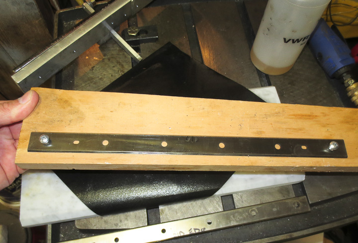
My planer blades are 13.5 inches of double edged sharper then a razor tool steel about 1/8″ thick. I found the best way to handle, move and store them between the planer and sharpening is by attaching them to a bit of scrap wood.  This eliminates any chances of accidental cuts or chipping the cutting edges.   After a couple hundred board feet of lumber goes through the blades need to be honed to allow for perfectly smooth surfaces on the boards.  As the edge dulls or worse gets a nick, it leaves raised marks and imperfections along the length of the lumber as it passes through the thickness planer.  It can be surprisingly hard to remove the marks left on the surface by sanding, making regular sharpening of the blades a must.

Hand sharpening planer blades  
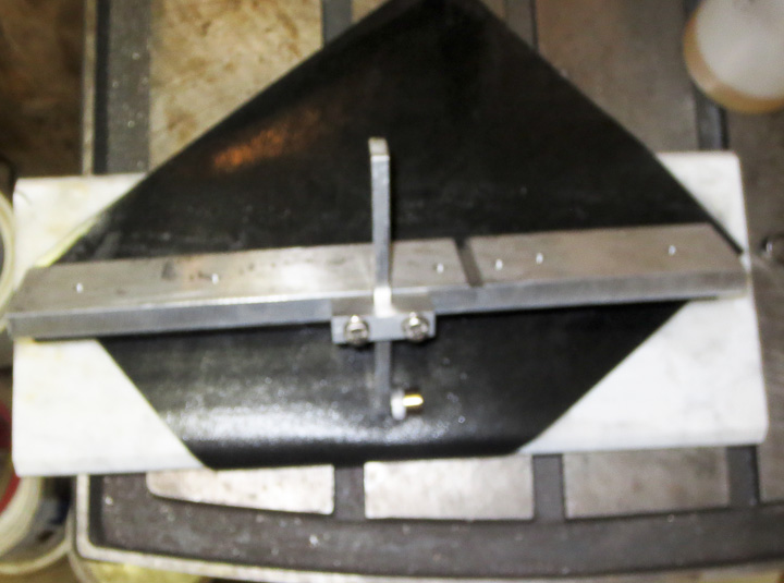
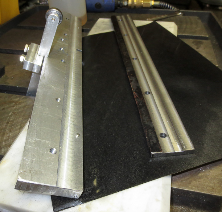
The sharpening jig I designed and built is pretty simple. I believe my original idea came from something I saw in Woodsmith or Wood magazine years ago.  In the past, it was reasonable to have my planer blades professionally sharpened (~$15 a pair)  or purchase (~$30 a pair) but today with rising prices (almost 50 bucks for sharpening and 90 for new blades) coupled with the increased frequency I need to sharpen them I can not justify the cost.  The jig consists of a bearing mounted on the end of an adjustable arm that allows for changes in the sharpening angle.  The arm is attached to the body which is essentially a stiff clamp that holds the blades parallel using two dowel pins for alignment.

How to sharpen 13 inch planer blades    13 planer blade sharpening jig-2133

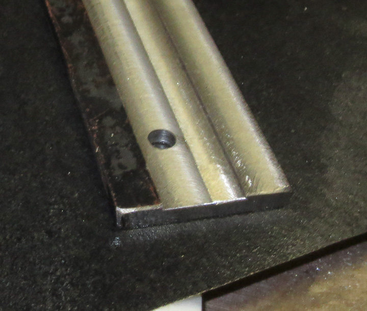
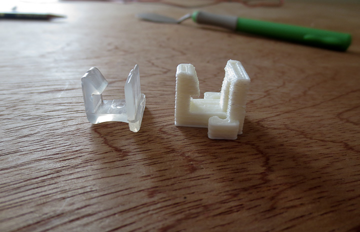
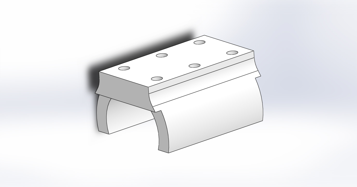
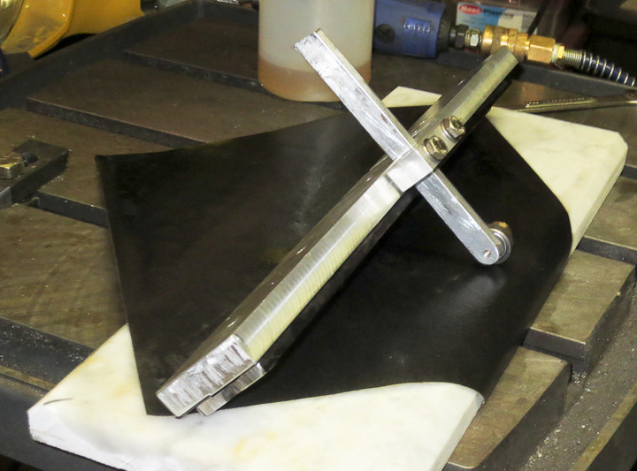
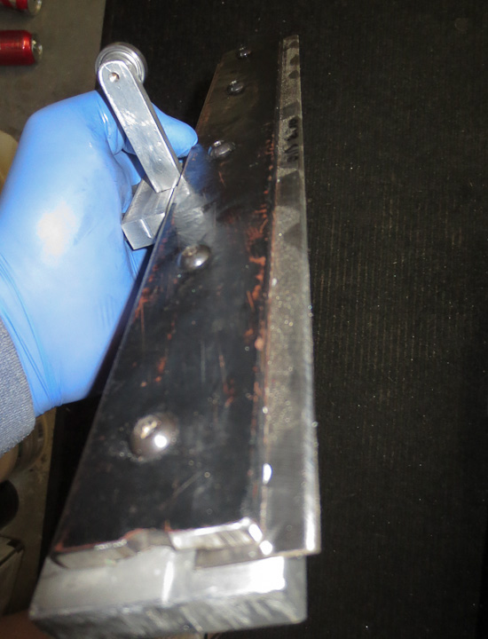
The above left photo shows the clamping piece,  it’s machined flat where it clamps down on the blade.  In addition the center is milled out so all of the clamping force from the machine screws goes onto the center of the blade. This is an important feature.  If you use a piece of unmmachined flat stock you risk having your planer blade rocking or being loose during sharpening.

a simple jig for hand sharpening planer blades

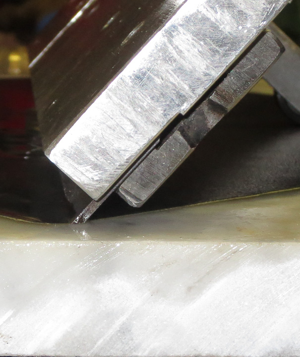
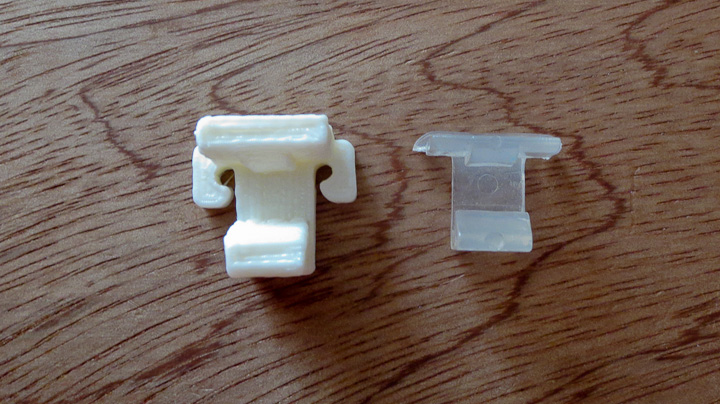
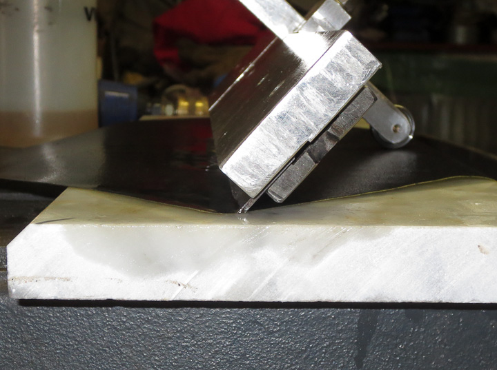
The above close up photo shows the blade clamped in the jig from the end.  You can see the milled slot and how it functions to hold the planer blade completely flat against the other half of the jig.

13 planer blade sharpening jig-2132      13 planer blade sharpening jig-2135

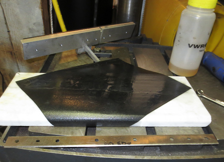
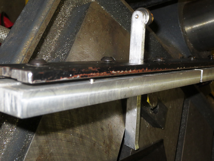
For a sharpening surface I’m using a piece of mirror polished Marble I had left over from some restoration work I helped a friend in Beacon Hill with a couple years ago.  It’s a hard flat surface.  I’m using wet or dry sand paper and emery (for the rougher treatments) to sharpen the blades on the marble slab.  Turned diagonal a standard sheet of sandpaper is wide enough to allow me to sharpen my 13.5″ planer blades.  Use plenty of light oil or WD40 to keep the metal particles from clogging the paper.

How to sharpen 13 inch planer blades     13 planer blade sharpening jig-2137

After careful initial setting of  the angle by adjusting the length of the bearing arm,  sharpening is simply a matter of olling the blade forward and back across the paper with light pressure.  This method takes 10-15 minutes of time  but the results are spectacular.  I usually go from 120 up through 800 grit paper when sharpening my edges.   As I have only used this jig for my longer planer blades to date, after the initial angle setting I have not had to change the angle again and a resharpening goes quickly.  I may make a second smaller unit for sharpening my 6 1/4″ jointer blades in the near future.   This handy little jig cost me nothing, as I made it from materials on hand, and has been used numerous times to quickly sharpen my blades saving me the time and expense of sending them out to be sharpened.

Enclosing your 3D Printer

3D printer enclosure finished-8272

With my 3D printer dialed in and tuned up, I was still having issues with the temperature on the heated bed and parts warping.  I determined that this was due to external air currents in the room.  I had been considering building a permanent table for the 3D printer and added an enclosure to my design to eliminate the effects of drafts on printed parts.  The enclosure is nothing fancy, very low tech in fact.  It is a corner framed box made from 1/4″ luan plywood with sliding plexiglass front doors.  It has handles and easily lifts off for maintenance and upgrades.

3D printer enclosure-8266    Enclosing a 3D printer -8270

The table is made from 5/4 pine lumber I had cut a few years back when the electric company cleared power lines along the property.  It has a full width drawer that slides out fully. I needed a place to hold  the tools and parts used to maintain the 3D printer in tip top shape. The small shelf in the back keeps the power supply and other wiring off the floor for better airflow and cooling of these units.

3D printer workstation -8267

For now, my 3D printer is driven by a computer and it has a nice new workstation courtesy of my good friends Mark and Michelle who donated the computer desk to the cause.  I also use this computer for development and programming of other projects like; Tetro the quadroped robot and Filastruder the filament extruder that will feed the 3d printer filament made from recycled plastic, and other cool things I’m not ready to leak to the public at this time. 🙂  Have no fear there will be blog posts on tetro and filastruder as I find the time.

3D printer LED lighted print head - 8275     3D printer LED lighted print head  -8274

Adding the enclosure required some necessary additions to the printer.  First was lights on the print head. I used to not understand why people would put lights on their print head, but now I get it.  When it’s running it’s important to monitor filament laydown and in the enclosure it’s pretty hard to do so without the lights.  I added three high brightness LEDs aimed at the print area to the left side of the x axis sled.

3d printer enclosure upgrade-8417

I used 12V SMT LED light strip which is readily available from online suppliers to light the entire enclosure.  The above photo shows the strip attached with a pressure sensative adhesive strip to the inside front of the printer enclosure.  The 30″ of light strip provides more then enough light for the enclosure.

3d printer enclosure upgrade-8419    3d printer enclosure upgrade-8418

Above photos show the effectiveness of the LED light tape.  Left photo lights off, right photo lights on.  A worthy addition to the printer.

3d printer enclosure upgrade-8421

What’s left to do to the printer before it is done?  My next steps will involve some changes to the control interface and enclosing the electronics that drive the printer (seen in the above photo).  These changes will turn my 3D printer will be a true stand alone machine with an LCD display, control interface via buttons and dials, and an SD card reader.    This will eliminate the need to have the PC running or even connected to the printer for operation. 


Using 3d printed parts to fix broken things

3d printed repair parts -duracraft fan clips-04

Everyone has a bunch of items around the house that are in need of a new knob, button, clip, etc.  Having a 3d Printer makes it easy to take care of these small repairs.  One might argue that it’s not worth the cost, but is it really?  Most parts needed for household repairs only use a few grams of ABS plastic when printed.  Given the relatively low cost of the filament, there is no where you could buy replacement parts (even if you ignore gas or shipping costs) at even 2x the cost of making one yourself.  I strongly suspect that in the future replacement parts will be printed on location rather then producing extras during a production run, cataloging, storing at a warehouse and then shipping them  to a consumer with a broken item. It’s far easier and cheaper to email a part file then it is to deal with logistics of supplying replacement parts.

3d printed repair parts -duracraft fan clips-02   3d printed repair parts -duracraft fan clips-03

I have had the same fan since I was in college. It is made by Duracraft, and of the free standing, oscillating type.  Over the years I’ve walked into it or knocked it over vacuuming a number of times. As a result, all of the small clips that hold the two halves of the wire fan guard had broken.  This was the perfect time for a repair with a 3D printed replacement part.  I took some measurements, quickly drew up the part in my favorite CAD software and printed one out.  My first version was not quite right, so I made some slight modifications to make it perfect.  In my design I included beefing up the strength of the clips by adding a little extra thickness to the part in critical locations based on where the originals had failed over the years.  Printing out 5 of these small clips my fan is once again good as new and I am safely protected from the spinning blade once again.

  Fixing things with 3D printing   Repairs with 3D printing

My repair clips for the fan are better then the originals, cost about $0.90 each in terms of filament used, and now my fan has been saved from being prematurely thrown out while it still has many more years of life left in it. 

3D printed repair parts - Rival High Performance Mixer -7925    3D printed repair parts - Rival High Performance Mixer -7922

  Similar to my Duracraft oscillating fan,  I had broken the power button on my Rival High Performance Mixer years ago.  I was still using it regularly but while making cupcakes one morning for a party, I realized I was sick of hurting my thumb every time I used my kitchen mixer.  I sat down after the cupcakes went in the oven and by the time they were done baking I had designed and printed the white slide button you see in the above photos.  It’s ergonomic, comfy and WAY better then the sharp bit of metal that was sticking up prior to my repair.  I seem to recall the original was the same blue as the “power plus” buttons on the side but I can live with my white 3D printed replacement.

3D printed repair parts - Rival High Performance Mixer

Once again, a useful household item was repaired at almost no cost for the repair part.  I doubt there’s even $0.30 in the tiny button I designed and printed for my Rival High Performance Mixer.  I expect to make lots of tasty things in the future with this great little hand mixer.

3D Printed repair parts - 2005 Ford focus window crank knob-7955    3D Printed repair parts - 2005 Ford focus window crank knob-7952

This last one will make all of my friends happy.  My peanut car (aka a  2005 Ford Focus) has had a broken window crank for years.  Originally broken on my side I swapped the broken one to the passenger side of the car.  I never really had issue with the broken crank, but everyone who rides in my car complains (or at least comments on it).  I did buy a replacement HELP! part at one point but it broke after only a short while.  I decided it was high time I fixed this as I was in a repair things mood and I drew up a replacement knob for the window crank, printed it out, and installed it.  It works better then the original part.  It is likely stronger then it as well.  ABS is a great material in terms of strength and impact toughness. The original had some flimsy polystyrene snap connector. I used an M4 bolt and washer to attache the knob in my design.  Someday I may even paint it black to match the rest of the car.

3d printed toys

In closing, 3D printing is not just for printing toys, or prototyping new designs.  3D printing can be used to cost effectively provide replacement parts for common household items. I read a paper recently that the Navy was retrofitting high end 3d Printers that can print in metal aboard all of the ships in the US Fleet.  This makes a lot of sense logistically, as they no longer would have to stockpile critical spare parts.  I can foresee that companies will someday offer replacement part .STL files directly to consumers to be 3d printed in the not to distant future.  With 3D printers now available at Staples and soon to be in every home much like an inkjet printer I feel this day is assuredly not to far off.


Upgrading your 3D Printer – x-axis improvements

Upgrading your 3d printer

After my initial excitement of having a fully operational 3d printer waned, I used the printer to produce parts to upgrade itself. Making itself better, stronger, faster than it was before. (How cool is it that the printer can make parts to upgrade itself??) Mass of the moving components limits the speed at which they travel and increase printing time. Inertia has to be compensated for in acceleration parameters as well. In short, less mass equals faster printing. The primary goal of printing replacement parts was to reduce weight of the moving components, the x and y axis sleds.  The Z axis moves very little and the mass is much less significant.  This post focuses on the x axis upgrades. The above photo shows the x axis sled with side by side comparison of the original (on the left) and the upgraded (on the right) components.  The left side is the original proof of concept machined aluminum bearing mounts and cross brace. The right side shows the upgraded 3d printed LME8UU linear bearing mount with a skeletonized machined aluminum cross brace that also lowers the print head slightly.

3d printed LME8UU bearing mount

 As you can see more clearly in the above photo, the 3d printed ABS plastic bearing mounts are considerably smaller then the original CNC machined aluminum design.  My plastic bearing mount raps around the bearing 20 degrees beyond 180 on each side for positive retention and due to the flexibility of the ABS snap over the bearing with a perfect fit.  The plastic mounts remove 18g of mass from each bearing.  The skeletonized cross braces come in at 8 grams in aluminum vs 36g of the original aluminum parts.  I did print them in ABS at 2g part weight, but they were a bit too flexible and I was concerned with heat from the making them softer still.

3d printed LMe12uu linear bearing mounts  skelotonized x axis sled

The upgrade of the linear bearing mount and cross brace resulted in 128g of mass removed from the x axis moving components. Also the bearing mounts applied a more uniform clamping pressure on the bearings then the CNC machined design, that when over tightened resulted in bearing drag.  As is often the case when building something, you design and build using the tools you had on hand. I always planned to replace the machined bearing mounts.  My original CNC machined aluminum bearing design was accurate but bulky, ugly, and heavy.

LME8UU bearing mount    

Above is a rendered image of my LME8UU bearing mount design.  The mounting holes are tapped M3 after printing and 10mm between centers. Here is a pdf technical drawing showing the dimensions : LME8UU bearing mount technical drawing.   I have added the linear bearing mount to Thingiverse.com as an STL and IGES file for others to use. Here is a link if you want to print your own 8mm linear bearing mount for a project:  http://www.thingiverse.com/thing:142243

x axis limit switch plate

All was not 100% perfect with the bearing mount upgrade, I did not consider the limit switch contact points when designing them.  I added a small aluminum plate using 2 of the 3mm tapped holes to solve this minor oversight.  Eventually I’ll add a physical feature to the 3d model and print  new bearing mounts for the two limit switches.  My original purpose in designing these LM8UU linear bearing mounts was as a universal part so that I can use them in the future for other projects.

wire mounting on 3d printer

Along with the weight reduction I moved the wire support to a more centralized location on the back side of the sled.  I felt this would help reduce strain on the wires during the repetitive movement along the x axis.  I orient my parts when printing such that the bulk of the printing travel is done by the x axis.   All in all,  these improvements along with other upgrades (to be shared in future posts)  have gone a long way to increase my printers speed, reliability, and aesthetics.