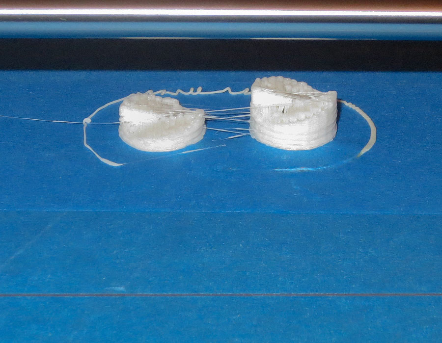
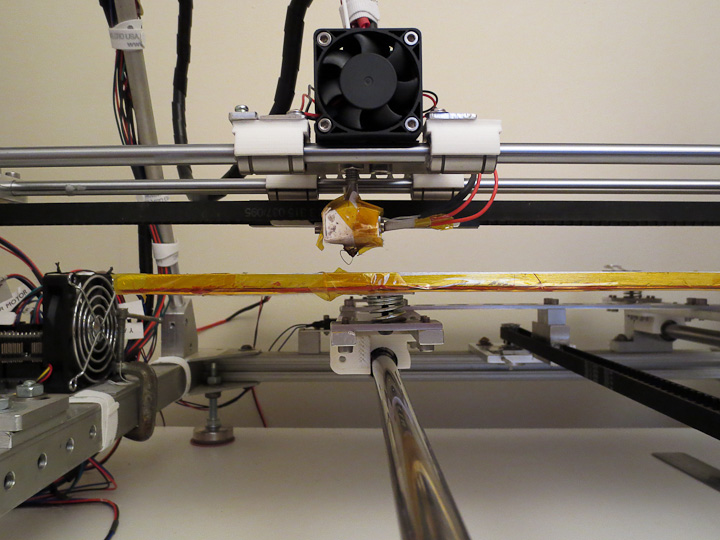
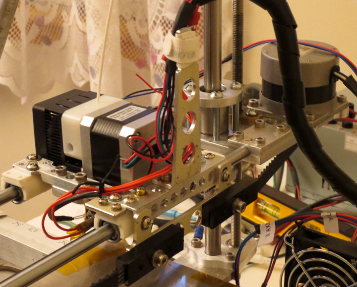
After my initial excitement of having a fully operational 3d printer waned, I used the printer to produce parts to upgrade itself. Making itself better, stronger, faster than it was before. (How cool is it that the printer can make parts to upgrade itself??) Mass of the moving components limits the speed at which they travel and increase printing time. Inertia has to be compensated for in acceleration parameters as well. In short, less mass equals faster printing. The primary goal of printing replacement parts was to reduce weight of the moving components, the x and y axis sleds. The Z axis moves very little and the mass is much less significant. This post focuses on the x axis upgrades. The above photo shows the x axis sled with side by side comparison of the original (on the left) and the upgraded (on the right) components. The left side is the original proof of concept machined aluminum bearing mounts and cross brace. The right side shows the upgraded 3d printed LME8UU linear bearing mount with a skeletonized machined aluminum cross brace that also lowers the print head slightly.
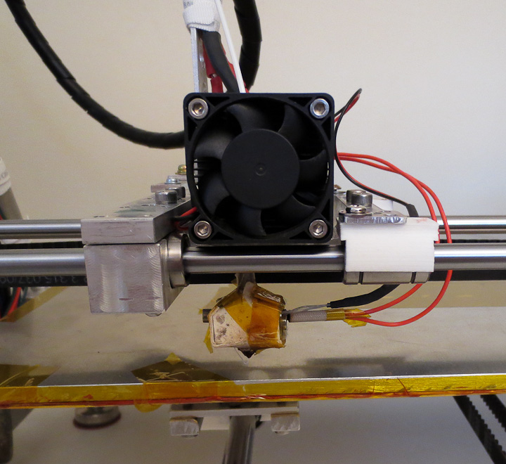
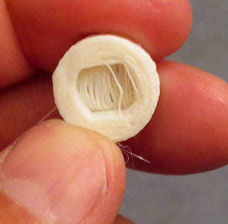
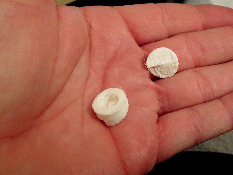
As you can see more clearly in the above photo, the 3d printed ABS plastic bearing mounts are considerably smaller then the original CNC machined aluminum design. My plastic bearing mount raps around the bearing 20 degrees beyond 180 on each side for positive retention and due to the flexibility of the ABS snap over the bearing with a perfect fit. The plastic mounts remove 18g of mass from each bearing. The skeletonized cross braces come in at 8 grams in aluminum vs 36g of the original aluminum parts. I did print them in ABS at 2g part weight, but they were a bit too flexible and I was concerned with heat from the making them softer still.

The upgrade of the linear bearing mount and cross brace resulted in 128g of mass removed from the x axis moving components. Also the bearing mounts applied a more uniform clamping pressure on the bearings then the CNC machined design, that when over tightened resulted in bearing drag. As is often the case when building something, you design and build using the tools you had on hand. I always planned to replace the machined bearing mounts. My original CNC machined aluminum bearing design was accurate but bulky, ugly, and heavy.
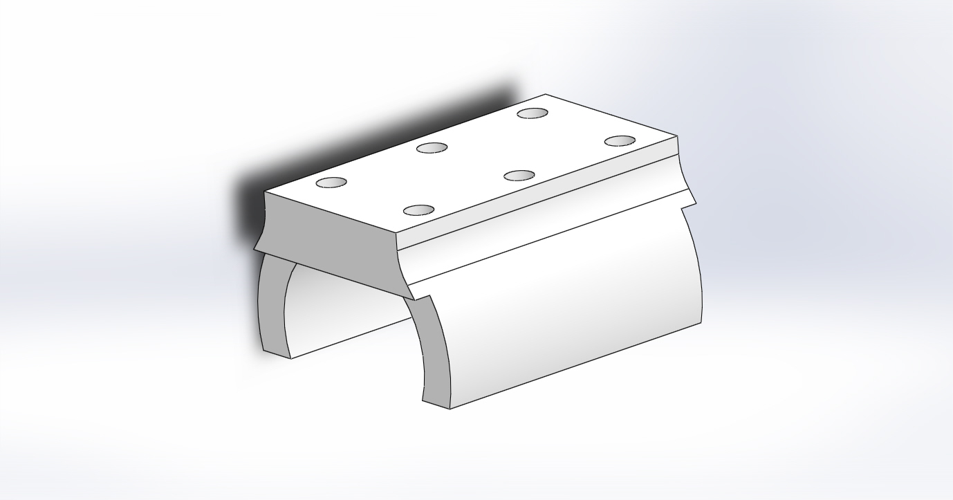
Above is a rendered image of my LME8UU bearing mount design. The mounting holes are tapped M3 after printing and 10mm between centers. Here is a pdf technical drawing showing the dimensions : LME8UU bearing mount technical drawing. I have added the linear bearing mount to Thingiverse.com as an STL and IGES file for others to use. Here is a link if you want to print your own 8mm linear bearing mount for a project: http://www.thingiverse.com/thing:142243
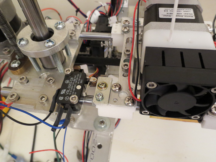
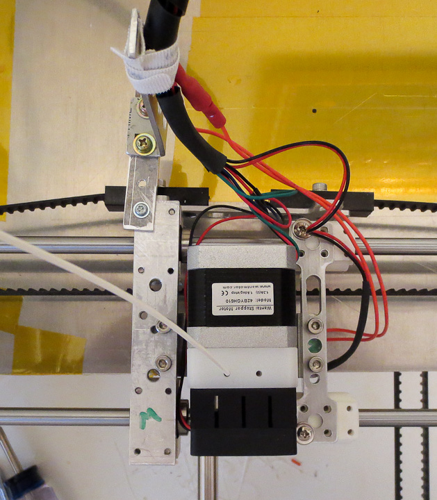
All was not 100% perfect with the bearing mount upgrade, I did not consider the limit switch contact points when designing them. I added a small aluminum plate using 2 of the 3mm tapped holes to solve this minor oversight. Eventually I’ll add a physical feature to the 3d model and print new bearing mounts for the two limit switches. My original purpose in designing these LM8UU linear bearing mounts was as a universal part so that I can use them in the future for other projects.
Along with the weight reduction I moved the wire support to a more centralized location on the back side of the sled. I felt this would help reduce strain on the wires during the repetitive movement along the x axis. I orient my parts when printing such that the bulk of the printing travel is done by the x axis. All in all, these improvements along with other upgrades (to be shared in future posts) have gone a long way to increase my printers speed, reliability, and aesthetics.