Tag Archives: linkedin

Cherry Medicine Cabinet

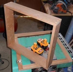
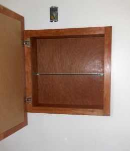
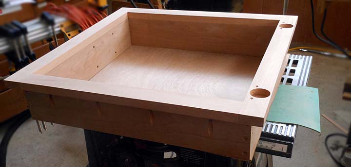
Last fall I ended up overhauling two of the bathrooms at the house.  Both seemed to fall apart at the same time which is not surprising as they were some 40 years old.  One of the bathrooms got a shiny new vanity along with the new floor and other bathroom items.  The vanity I selected had no option for a  matching medicine cabinet.  No store bought cabinet would fit the atypical opening in the wall.  Months of staring at a gaping 2’x2′ hole in the wall  got old.  I decided that the first of the year would be well spent making a new medicine cabinet to fill the ugly hole in the wall.  It actually took the 1st and 2nd day of the year to build. I blame that on having only 3.25 hrs sleep on the first due to fun new years celebrations.


I chose basic construction practices for the design.  I made the entire project from a single cherry board I milled back in the summer.  The tree had been 2 years dead standing prior to my milling it into a board and the wood measured dry enough.   I used basic rabbit butt joints on the box with some 1.5″ brass screws I had on hand.  I assembled the face frame with pocket hole screws.

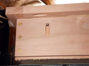
pocket hole screw joints  

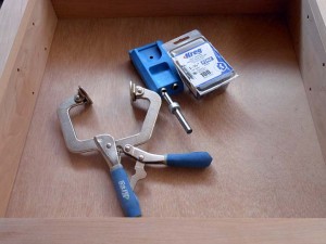
Pocket hole screws (above left photo) are one of the best things ever for cabinetry and quick strong construction.  I bought my KREG pocket hole jig  (above right photo) when they first came into their own while still in high school.  Pocket hole screws are put in at a 15 degree angle and quickly clamp and secure wood pieces together.  The KREG jig is the greatest of all modern woodworking innovations in my opinion.  It allows you to quickly build cabinets, boxes, face frames, etc.  I’ve used it to screw in studs and braces in rough construction. I have built many cabinets with it.  I even used it when I built my regatta winning boat one summer because of it makes for quick easy joinery.  It used to be, one had to go to a woodworking store to buy the pocket hole screws and jigs but they are now sold at Lowes everywhere.


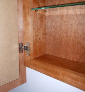
The cabinet came out well.  I had to invert the cabinet hinges to make them work with the mirror.  The cherry I selected matches the wood on the mirror well enough that you might think they came together.  I added shelf pins and bought some 1/4″ plate glass at Granite State Glass in Concord for the middle shelf.  I may get a second shelf, and drilled the holes for one.  Right now I think I like it with just the one shelf.  Granite State Glass is the place to go for any of your project glass or mirror needs in New Hampshire.  They are friendly, affordable, and always willing to help me when I’m not certain what grade/thickness I might need.
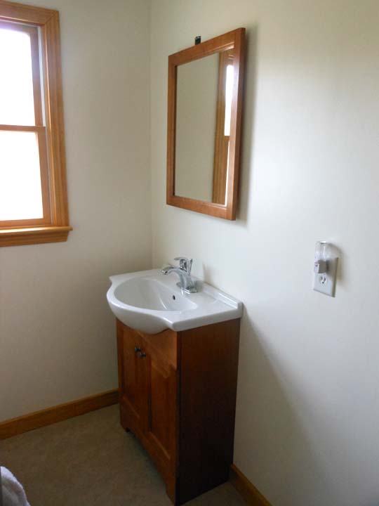
I’m pretty happy with how my cherry medicine cabinet came out and with how well it matched my St Pauls Chelsea vanity/sink.  Now all I have to do is come up with or select a light to put over the top of my new cabinet/mirror to complete the bathroom renovations.
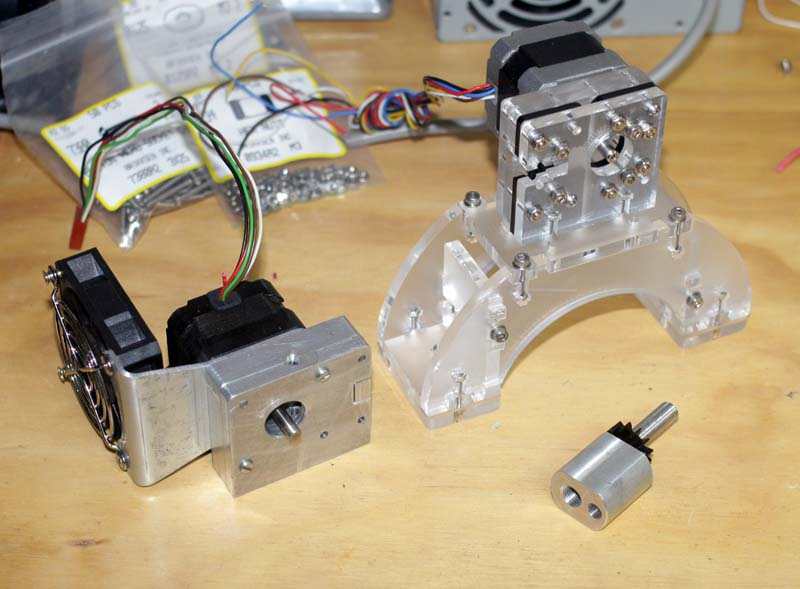
Assembling a Makerbot Mk6 Stepstruder

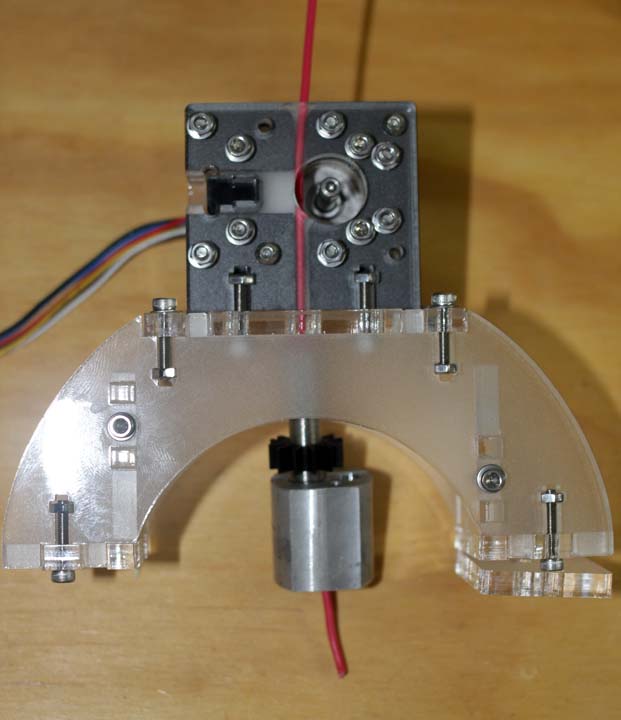
stepstruder mk6 compared with my cnc machined plastistruder

The reprap 3D printer project has been on hold while I work on other more critical items like upgrading the cnc machine and the holiday rush. I’ve got some pretty awesome friends who help me out with projects.   This Makerbot Mk6 stepstruder was cut by one of my very good friends who happens to have access to a laser cutter at work.  I supplied some acrylic and delrin sheet.   When he had some time he stayed late after work to cut them out for me.  Laser cut parts are a thing of beauty, especially in the frosted acrylic as there is a nice contrast between the crystal clear sides and frosted faces.  Sadly I forgot to take pictures during assembly so here’s a link to the makerbot assembly instructions.  I need to get a small digital camera for the shop area for project documentation.  I promise to get better with this in the future.


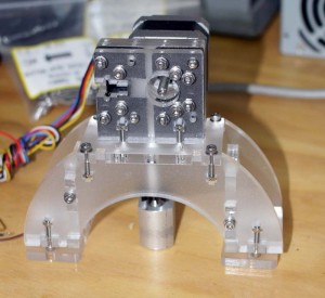
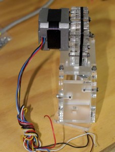
The Makerbot Mk6 extruder is an elegant design. I really like the use of captive nuts and m3 screws to hold it all together.  For final assembly I will use acrylic adhesive.   I need to order and make a few parts for this unit.  I plan on running it side by side on the bench with my cnc unit.  Experimentation when they are both complete will determine which is a better print head / plastistruder for my 3d printer.   I realize that I will need to do some significant lightening of the CNC plastistruder I designed to compete with the mk6 stepstruder in terms of mass/inertia.

The picture above shows the “filament” going through the plastistruder.   The print head for the Reprap style 3D printers is basically a micro sized extruder for molten plastic.   A plastic wire, is fed through a sharply cogged pulley (missing in the pic) into a hot nozzle/head unit (the aluminum bit down bottom).    Continually feeding the hard unmelted filament into the tightly fitting tube causes pressure to rise and the molten plastic to be extruded through the nozzle on the bottom (also not shown, use your imagination please).   The computer will control the rate of extrusion and match it to the speed at which the printer is moving to produce a uniform printed layer of plastic.  That’s the basic idea behind the Reprap based print heads.  They have undergone a continual evolutionary improvement and will continue to do so into the future.  I love the open sourced community nature of Reprap development.  You get parallel and divergent development as different people work on their own units and try different things out.

My low cost three axis CNC controller


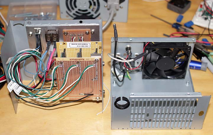
three axis CNC controller build - insides

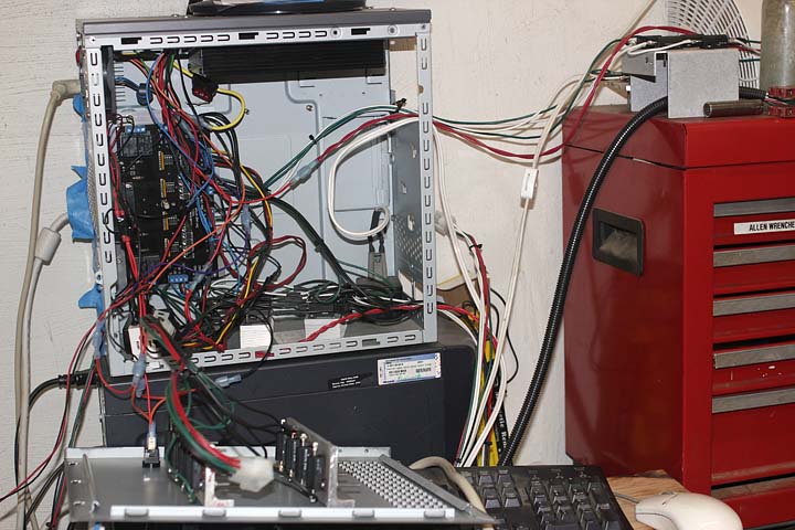
I recently decided that it was high time to upgrade the original electronics I built for my CNC milling machine conversion on a RF7045 style milling machine.  The original electronics, shown below in the mess of wires and full size metal enclosure,  used a unipolar 4 axis control board and huge banks of power resistors to limit current.  It was poorly thought out and an ugly mess, but fully functional  The drawbacks to the original set up were primarily excessive heat generation (overheating in the summer) and an inefficient design.  Unipolar driven stepper motors produce considerably less torque then the same motor driven by a bipolar controller.   It was also a huge ugly mess with wires everywhere and heat sink banks outside the box.  The upgrade to the new CNC control unit was all spawned by Pololu’s black friday super sale on all of their great robotics and motor drivers.  If you haven’t been to Pololu’s website, definitely check out their products. Very good stuff at a good price, and on Black Friday 2011 a very very good price.


original unipolar four axis cnc controller hooked up to the RF 7045

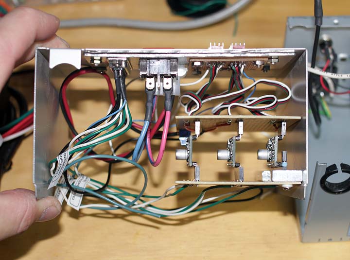
The new low cost three axis CNC controller uses three Pololu A4988 stepper drivers in what I call the “Tie Fighter Configuration”.   I’ve  sandwiched them perpendicular to two larger circuit boards creating a channel for air flow.  With a   high velocity cooling fan and a custom heat sink mounted to Allegro’s A4988 microstepping bipolar stepper motor driver chip I hope to use these at or close to their 2.0 Amp max rating.  Eventually, when my reprap 3D printer is completed, I’ll print out a fan shroud to further increase airflow over the chips.  The data sheet for the A4988 is here,   pdf of the website for the pololu board is here,  current pinouts for board are here.  (data for me in the future)  As I continue to add or improve the CNC controller I will update this post.

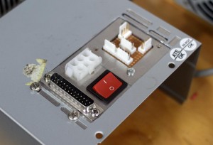
million out the control panel for the ver 2.0 cnc controller  I/O board for the low Cost CNC controller

 The first version of my cnc controller had wires coming out of it connecting to the steppers.  This turned out to be terrible in use and was very unclean.   Version 2.0 had to have external mounted plugs for all of the external connections to the stepper motors, limit switches, power supply, and computer.  A bit of research on connector dimensions, a bit of CAD design, converting CAD to g-code (cnc machine program language) and the cnc machine running on the v1.0 cnc controller machined the next generation I/O board you see in the sequence of images above on the left.   In essence my CNC machine built parts to upgrade itself.  I think this is the coolest thing ever!  Having a machine that can make upgrades for itself.  Not quite self replicating like the Reprap 3D printer project but still pretty exciting stuff. As a kid this was the thing of Science fiction and not reality.

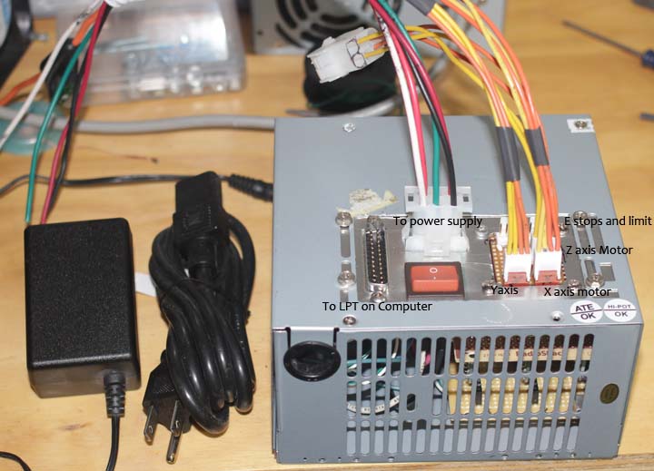
Connections to the milling machine and power supply labeled

The connections are labeled in the above photo showing the pre-testing assembled unit.  Post testing I realized I should add an on LED to the top as a main power indicator,  along with an LED indicator for the cooling fan power.  I ended up not being able to scrounge a usable DC/DC power supply chip.  I wanted to use a DC/Dc converter to  internally converting the 33V from the power supply into 12V for the cooling fan.  Instead I ended up using  a wall wort (aka plug in dc transformer) to supply power to the cooling fan and added an external plug jack to the case.   The bad part about this set up is there is no interlock.  In theory,  I could run the controller and not have the cooling fan powered up resulting in some sort of thermal meltdown.  The Ver 1.0 CNC controller had dozens of similar issues.  I had hoped to avoid this situation in this unit.   I plan to order a dc/dc converter  from Digikey in the near future and add the power for the cooling fan internally to prevent the possibility of thermal meltdown.

The above picture is of the “Tie Fighter Configuration” I’ve created.  The three little Pololu A4988’s are stacked in between the top and bottom boards.  This should create a nice cooling duct for the air supplied by the cooling fan to run over them to remove excess heat.  I will also make some copper u style heat sinks and mount them with Akasa double sided heat sink tape.  I’m hopeful that with this set up I can drive these little boards at close to their 2 amp max rating.  The CNC machine also made the aluminum bracket that mounts the boards to the right side of the case. More self upgrading on the machines part.  The Pololu’s are being run in their most basic configuration, ie. full step, with only step and direction imput from the computer to each board.   The three axis CNC controller also has a built in NC (normally closed) chain of limit switches and an E stop.  This set up uses a pull up resistor on the computer side.  When any one of the grounded NC switches is hit the output goes high and the computer instantly shuts off power to the motors sensing a mechanical limit or emergency.   Limit switches and an Emergency stop switch are necessities on any CNC controlled machine.  They keep  those G code programming errors from breaking something.  I’m using pc side controls, rather then the on board enable/disable built into the Pololu A4988 boards.

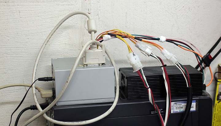
New three axis CNC controller in place and connected


Here she is, all hooked up and running the machine.  The Akasa heat sink tape has not arrived in the mail yet.  The CNC controller was run at only 0.7 amps for “testing” purposes.  Everything hooked up and worked well.  I was half expecting something to go up in smoke.   I am very pleased with the considerably smaller and less complicated version 2.0 CNC controller.  This new unit will drive the motors with about 40% more oomph which means faster machining time for me.    This is an ongoing project and I’m sure  I will continue to add and evolve in the coming months.  I’ll post more as I make changes.


Shaker inspired dining table – finished

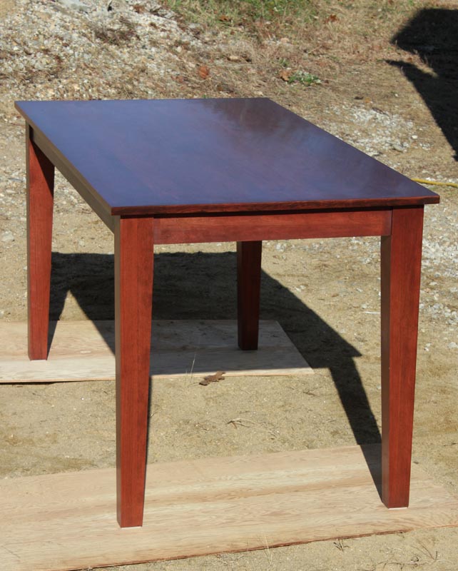
Cherry Shaker inspired dining table

Here are some pictures of the stained and polyurethane finished table.  The stain is an old masters rich mahogany. I could say a lot about the old masters stain but I’ll just say this, I won’t be using it again.   The table came out well and I’m quite proud of it.  It took considerably more coats of urethane on the top to seal all of the wood grain then I expected resulting in a bit of a delay in being able to deliver this table to it’s  happy new home.  I’ll be delivering it tomorrow and it should provide many years of lasting service as the family dining table.

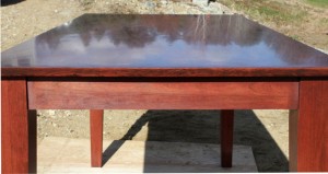
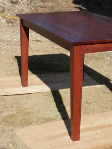
Cherry Shaker inspired dining table     Cherry Shaker inspired dining table

The top finish is a satin non gloss, but the depth of the 8 coats of urethane goes a long way to have that deep reflection in spite of the lack of gloss.  I’m pretty happy with the final product and I know my customer will be happy when she sees her new table.