Cafe Racer build continues

I started in tearing down the front end tonight.  I’ve got a fairly firm plan as to what I will do going forward.  The good news is the brake caliper is good and does not need to be rebuilt.  Bad news is the MC needs to be replaced completely.  I knew about having to do one thing or another to the front brake set up on this bike before I went to look at it so I am not surprised.   I’m toying with clamp on on bars vs clubman style handlebars.  Needs a bit more thought.


I went through, tore the parts down as needed and cleaned out the varnished fuel, freed up the floats and generally gave them a light buffing.  I’m not going to polish them at this time because I might black out some or all of the carb bodies.  The carbs are ready to go back on the bike for some test riding around the yard in the near future.

CX500 brake Caliper of the bike      Honda CX500 Handlebar Mount

The Brake caliper in the left pic looks and functions well.  Bonus on not having to rebuild that.  I will clean it up a good bit and grease the pins prior to putting it back on the bike.  The Right pic shows the handlebar mount. I’m not certain what I will do here.  I suspect I may fire up the cnc machine and make a new top clamp piece eliminating the fuse housing to streamline the front of the bike.  The bike is wired with ridiculously fat wire throughout.  As part of the build I plan on addressing the excessive wiring somewhat.  I’d like to have only one small gauge in a bullet style headlight pod if possible. Maybe have a small digital unit as well.  I will make a small LED based indicator board for directional indicators, high/low/headlamp lights, etc.   I’d like to have nothing but I want this bike to be easy to ride on the street with some rider conveniences.

Reprap 3D Printer progress and photos

One of the corner angle mounts for my Reprep printer being made on my CNC machine.   As a kid, I was a huge fan of Science Fiction Novels, but never did I really believe I’d see the day where I’d have a robot, that would make me another robot that could then replicate itself.  I think one of the greatest things of our era is the ready access to programmable chips like the ATMEL ATmega series.  These are the processors used on the very popular Arduino and Sanguino boards.  My Reprap will be powered by Sanguino running on an ATMEL atmega eventually.   More on this topic in a later post.  Today is all about showing bits and pieces of my reprap 3d printer.

Reprap 3D printer Y axis WIP        reprap 3D Printer Z axis and x Axis drive side

The Left picture shows the Y Axis set up.  The build platform will be mounted to a carriage that runs on those four 12mm  linear bearings that are seen in the picture running through the center of the chassis.  I need to get a belt with 19 less teeth then my current or cut the belt and clamp both ends to the carriage (the 1/4″ aluminum  square in the pic).  The pic on the right shows the Z Axis as well as the drive motor on the X Axis.  The X axis will have the stepstruder printing heads on a carriage moving on 4 8mm linear bearings.

Reprap 3D printer Z axis other side       RepRap  CNC machined stepstruder print head

The left pic shows the idle side of the X axis as well as the other side Z axis.  I chose to go with the dual stepper motor Z axis over the belt driven dual leadscrew set up.  I have tested it with my zac built stepper driver set up run by a 555 timer pulse generator circuit to drive a pololu A4988 and it works well.  I imagine I’ll have to check for lost steps and align the printer periodically with this set up.  The right hand picture shows my milled stepstruder.  It’s roughly based on the MK6 Stepstruder sold by Makerbot with some Zac-provements.   I still need to order a heater cartridge from them and machine the shaft, heat break standoff and some other pieces to finish the plastistruder unit.  Eventually I hope to have a double extruder head set up so I can run a water soluble support material on one head and the build material on the other, or to do multicolor builds.


My RepRap based 3D printer

This post will catch my readers up to speed on my 3D Printer project.   It’s design is loosely based on the current RepRap Mendel and Prusa Mendel 3D Printer Designs.  My goal was to build as much of my 3d printer from what I had on hand.  I started this project back in May of 2011.  I’ve been working on it in my spare time and having my CNC Mill do 95% of the manufacturing of components for this project.  It’s been a good way for me to build CNC programming experience as well as test out the capabilities of my CNC milling machine (based on the popular RF-45 model Mill Drill) to determine Gen 2 upgrades needed to the CNC Mill.

My Reprap project is partially inspired by the fact that I had a prototype Objet Alaris 3D printer for evaluation for work for 9 months prior to their launching of that product.  It was mostly product testing and a bit of debugging for Objet but it gave me a full taste of having 3D printer access all the time.  I still have and use many of the components I printed out for the house, my zacbuilt engine driven TIG welder, and of course in the Datsun  and Mustang.   3d Printing, also often refered to as rapid prototyping, is the greatest thing to come along since the advent of CNC machining for the fabricator.   It’s often faster to design a part virtually and just print it out then to try and make it by any other means.  It’s a great way to test out crazy ideas, various styling changes, and tactile features of a design.

Reprap Gen6 electronics      reprap CNC machined Stepstruder plastistruder

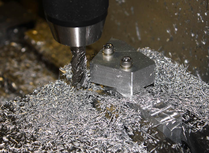
My RepRap 3D printer will be driven by Gen 6 electronics.  This SMT board drives all three axis, and the stepstruder (aka plastic extruder printing head as shown in the right pic above) all in a small low power package.  My first go at acquiring a Gen 6 board did not go so well and I ended up returning it.  The board had numerous poorly soldered joints and one chip was floating off board at 20 degrees with several pins in the air.  I since decided to finish the mechanical before reacquiring another Gen 6 board.  By the time I’m ready to fire it up there might even be a better next Gen board design available.

I think I’ll close this post here,  I’ll share more about this project over the coming days to get caught up on where I am to date so I can move forward with the next steps.


CX500 Cafe Racer Project Day 1


After the first evening of working on this project I’ve got the back half of the bike somewhat torn apart. I’ve got a solid plan as to where the electronic components will go up under the seat pan.  I’ve been looking at tail lights and I believe I’ve found one I like enough to “settle on” for now.  It’s an all in one LED unit with a license plate mount and led plate lights.


  The red line in the above photos shows where I plan to cut off the rear seat frame.   I plan to fabricate a new seat mount to weld in place before I make the cut and finish off the end of the upper frame.   The more I toy with the design in my mind the more I feel like I will either scallop the fuel tank at the back, or possibly fabricate a new tank entirely.


In other exciting news, I got the ugly factory air box off.  The carbs weren’t drained when she was stored and the fuel varnished inside. They are coming out and apart.  How much of a rebuild I do will be determined after I tear into them and investigate their condition.   The right hand carb has the float stuck down and the fuel comes out at a good clip when she runs.