I’m skipping ahead in regards to order things happened in the rebuild as many friends are interested in this particular topic and I do not want to write to each of them explaining how it works.
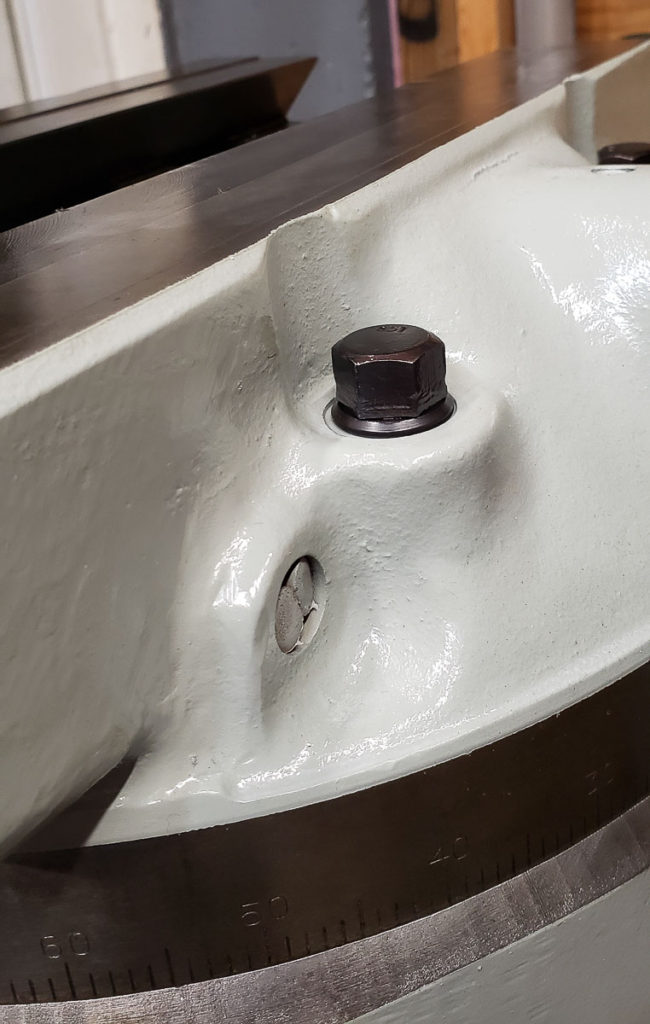
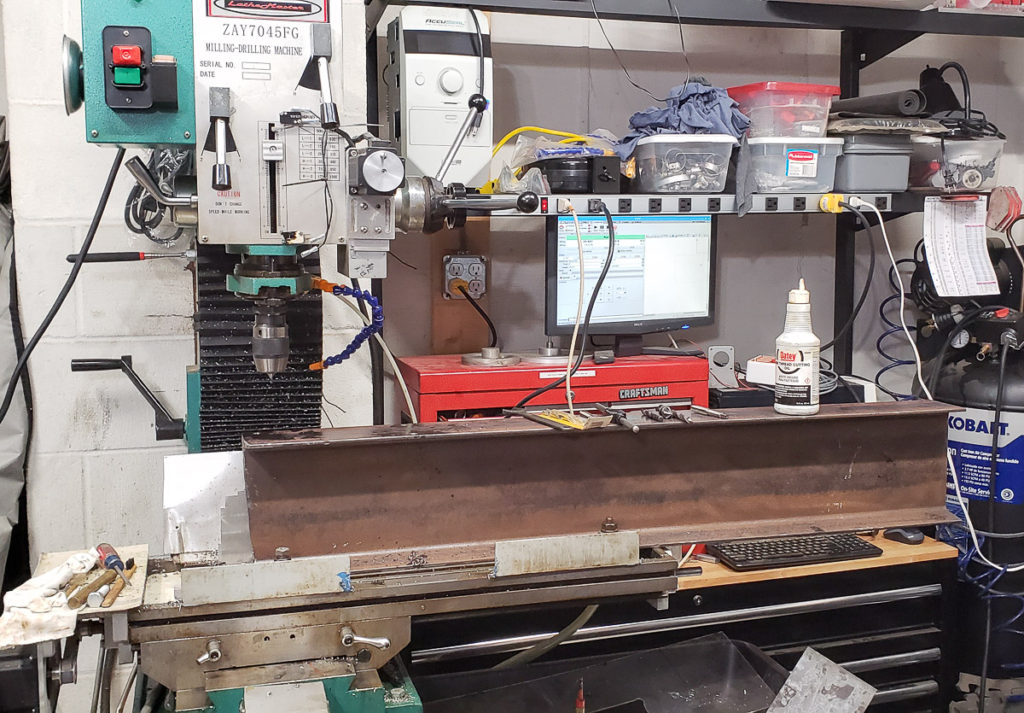
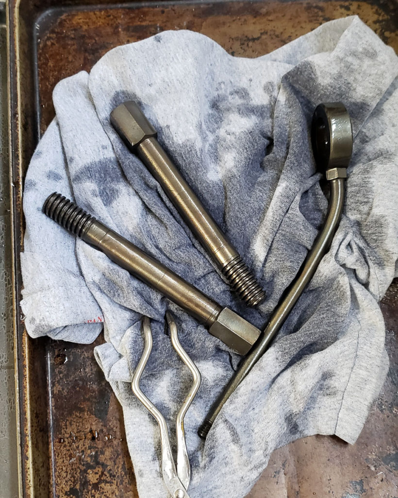
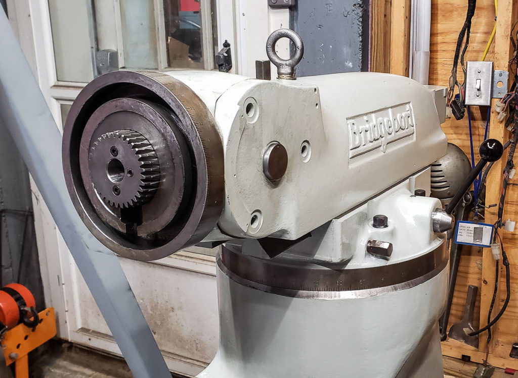
In addition to restoring the castings and mechanicals on my Bridgeport Milling Machine I scrounged late last year, I needed to restore or replace the hardware. Replacing hardware can get expensive quickly. The hardware on the mill was all very servicable, but very ugly. I opted to clean, polish, and refinish all of the hardware. I am a huge fan of Black Oxide or Blued finishes on steel. While not suitable for exterior applications, this helps keeps hardware used inside from rusting prematurely. Plus, as you see in the photo above, the black hardware contrasts nicely with the Industrial Light Machine Grey paint I used on the castings after stripping them.
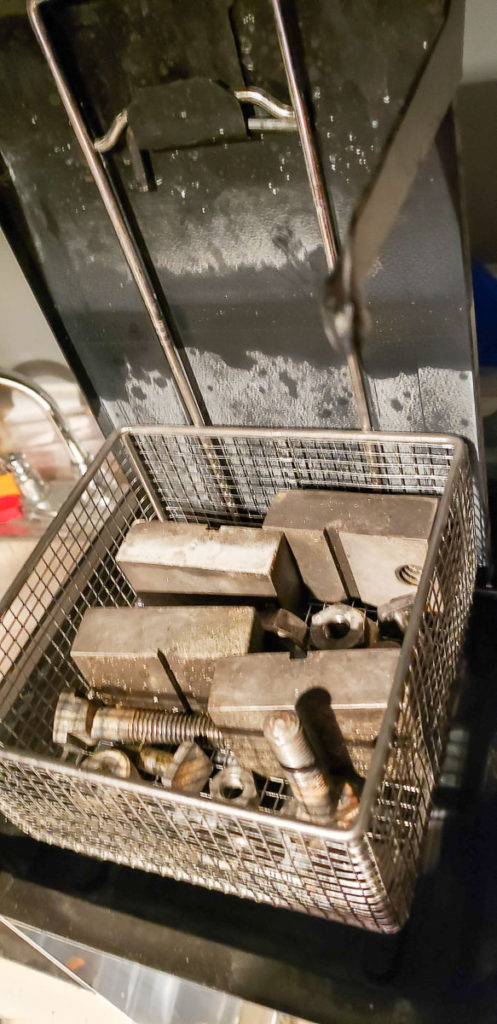
Refinishing hardware is a bit labor intensive. Thankfully the Bridgeport uses relatively few nuts, bolts, and washers in assembly. I start hardware restoration by bulk degreasing and washing all of the parts in an old FormWash which agitates the bath and has been modified to heat the de-greaser to better clean components. I use either Simple Green or Castrol Superclean without dilution as a degreaser which works well, especially heated up to about 50C. You can degrease a surprisingly large number of really nasty dirty parts and engine bits in this before you need to change out your degreaser.
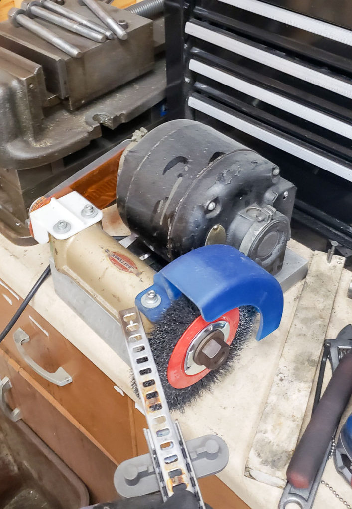
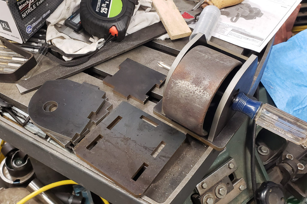
After degreasing, I spend a few minutes on the wire wheel buffer I built polishing the hardware to shiny bare metal. I’m not looking for mirror finish on the parts, but I do ensure no grit, grime, rust, dirt, or burrs remain. I will touch up dings and “Gorilla wrenching” marks with a fine double cut file and rebuff when I find them. I run taps through the nuts to ensure the threads are cleaned out.
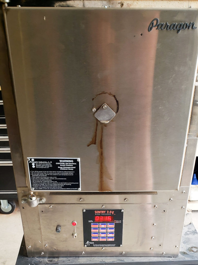
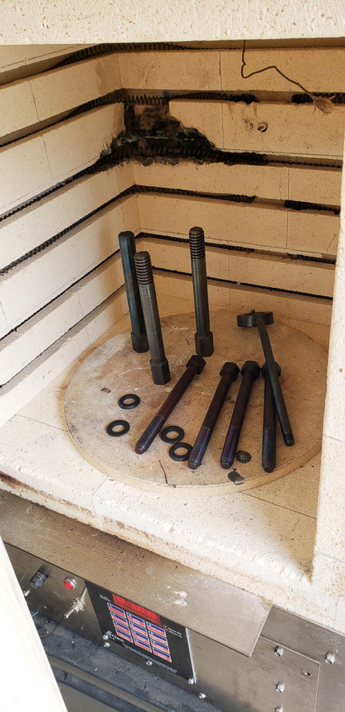
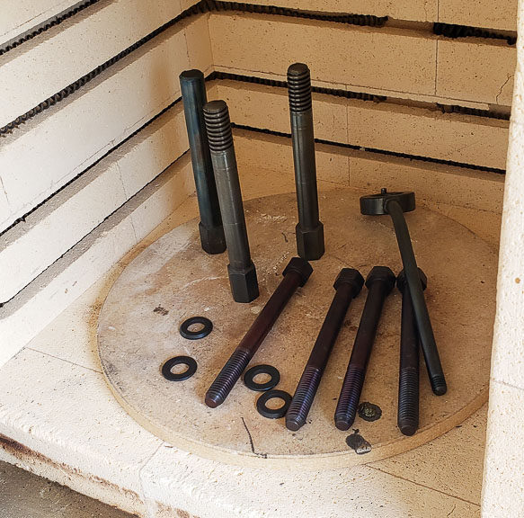
After cleaning and prepping the hardware the next step is to preheat your furnace to 300C. I have a very nice Paragon furnace I scrounged. It was wrecked when I got it due to some experiment gone horribly wrong. I managed to restore and fix this furnace to almost perfect working condition with very little cost. It’s quite large inside and capable of holding temperatures up to about 1100C.
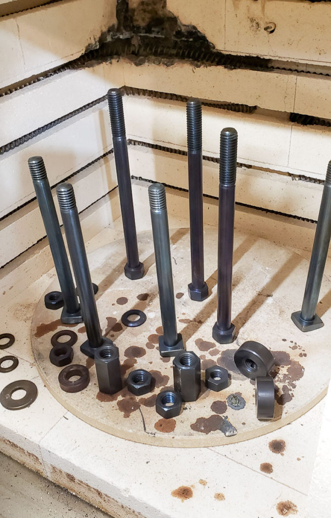
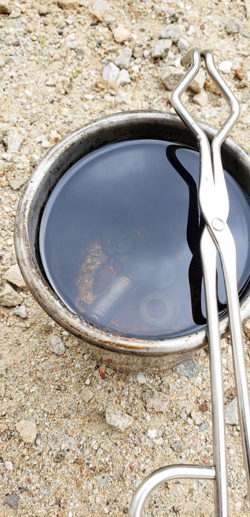
This is not the modern process of blackening steels that uses salt solution baths. This is more of the DIY, slower old school method. The process involves heating your clean, dry, parts at 300C for an hour or two, then you dunk them in a nice oil. I am a fan of Canola (rapeseed) oil for this dunking. You can repeat these steps if you want a darker heavier finish. This process leaves a nice hard blue-black finish on your steel. The alloy and part size and shape do affect this process a bit. So all of your parts may not end up quite the exact same shade of black. Dwell time and contaminates can cause differences in color as well.
I originally saw this process in a video restoration of an old Vise that my buddy Brian shared with me. This is that vice restoration video which is wonderfully put together: https://www.youtube.com/watch?v=U2jNeObHnZY The video is well worth the time to watch as it is very well done.
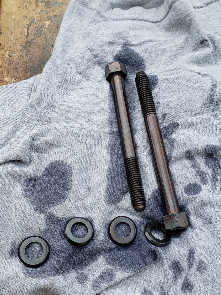
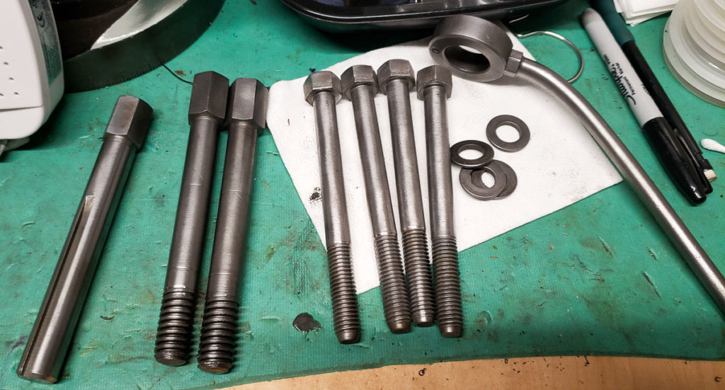
The newly blacked parts get sprayed with a solvent wash to remove the canola oil residue which might varnish over time. I then liberally coat them with Vactra way oil or a nice 30W motor oil before installing them back into the mill.
On the mill the freshly blackened hardware looks fantastic. I am glad to share this trick. It is a nice quick way to give old hardware a new fresh look in a restoration. I like that it doesn’t require multiple baths of nasty caustic and salt solutions compared to the modern industrial process of hot or mid temp chemical conversion coating to black oxide.