Building a wood canoe yoke from rock maple

Canoe Yoke Installed on my Canoe

I recently picked up a very nice small canoe for summertime fishing and adventuring on the water.  The price was right and it was exactly what I wanted so I made the deal and brought her home with me one night.  It’s short (13′), wide making it stable and has two seats so I can bring a friend.  This is an improvement over my kayak primarily due to the bring a friend factor.   My new canoe needed several things before I took it on the maiden voyage.  First and foremost it needed all of the 1″ oak seat spacers replaced.  I made some new spacers from a 3/4″ oak dowel I had in the shop.  The second thing it needed was a yoke.  At some point in the past, someone removed the yoke from the canoe .  The yoke helps stabilize the sides and provides an easy way for single man portaging of the canoe by throwing it over your shoulders to carry.  This will be a mostly pictorial post.
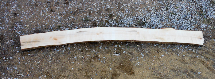
Selecting the rough maple board for the canoe yokeThe first step in this project was selecting a maple board from my hardwood lumber pile that I cut with my Alaskan Sawmill featured in previous posts.    My choice in boards was limited by what I was able to get out from the bottom of the pile.  It was a bit like playing Jenga removing one of the early boards.  This was one of my first boards cut with the Alaskan sawmill last summer and it was far from beautifully cut.  Thankfully I cut all my boards a bit extra thick so I could mill it into dimensional lumber.  I love that I am now building things with lumber I made myself from storm downed trees.
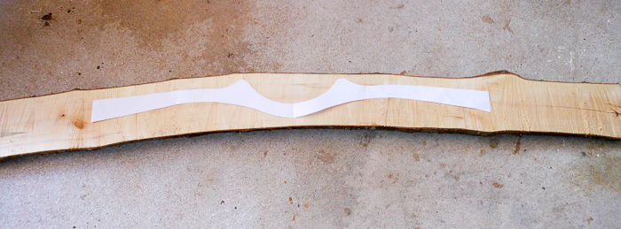
checking my canoe yoke pattern on the rough boardAfter selecting the rough maple board, I placed my paper template onto the board to find the best fit in terms of grain and avoidance of the knots.
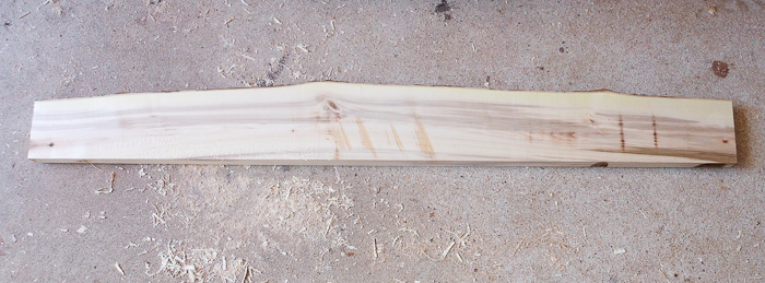
Straightening squaring and planing the rough lumberThe next step was to cut the ends off the long board. I will use the scrap bits to make small projects like my wooden baby rattles that are available here.   Then I cut a straight edge on the board using the bandsaw, being mindful of where I wanted to cut my yoke out and leaving plenty of wood.  Then a few quick passes on my jointer and I had two adjoining sides flat and squared up.
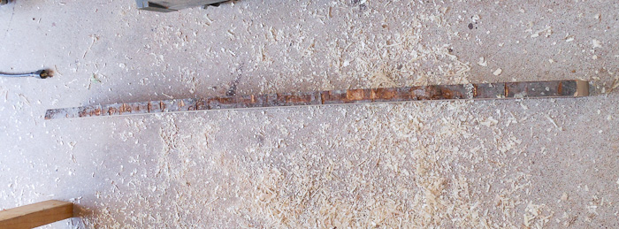
dimensional lumber stock for making a canoe yokeAfter the jointer flattened out one side,  the board goes through the planer and voila, perfect thickness lumber is born.  I wanted my yoke to be sturdy and Zac tough, so I planned the rock maple to a 1″ thickness.
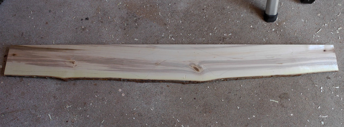
Trace the Canoe yoke pattern onto the boardHard to see but now that the lumber is dimensioned on three sides, I traced the paper pattern onto the board.
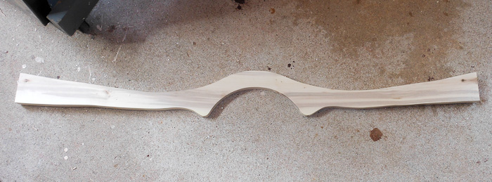
rough cut canoe yoke before sanding and routingHere is the rough cut yoke after being cut out with a jig saw.  I might have used the bandsaw but I had the wrong blade on it.  Sometimes it’s easier to use a different tool then to change the blade.  That’s why I used my jig saw for this project.
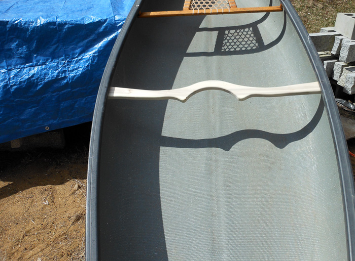
I did a dry fit of the yoke, carefully measuring and cutting it down to size.  It came out perfect and is a gentle snug fit inside the hull.
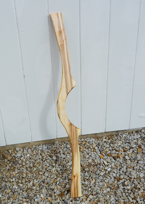
Here is the canoe yoke all finished but not yet installed.  I realized I didn’t take a pic of the finished yoke installed on the canoe.  I’ll take one tomorrow.  Hopefully I will have my maiden voyage tomorrow or the next day and get to try out carrying the canoe with my newly installed yoke.

Maiden voyage of my Canoe with the new wooden Canoe yoke on projectsbyzac.com Quick update, Above is a photo of the yoke on my maiden voyage in the new Canoe, and I wanted to share the wooden canoe yoke pattern files with folks since I have noticed there was interest in wooden canoe yoke pattern for downloading.

If you want to download the canoe yoke pattern I used, here are the files:

Canoe Yoke Pattern 1 of 5

Canoe Yoke Pattern 2 of 5

Canoe Yoke Pattern 3 of 5

Canoe Yoke Pattern 4 of 5

Canoe Yoke Pattern 5 of 5

Download and print out the Canoe Yoke Pattern PDFs unscaled, cut them out and tape them together.  You will then have your template to make a wooden canoe yoke of your very own.   Hope this helps


New Hampshire Maple syrup making – the 2012 experiment

Taps and Buckets on Maple Trees

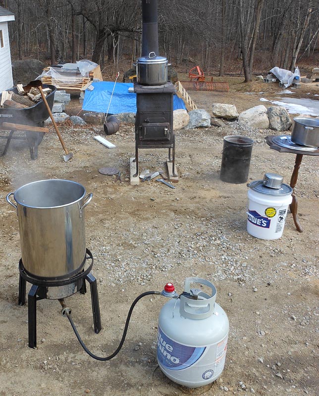
Every since a childhood trip to a local sugar shack, I have wanted to make my own maple syrup.   A couple years ago I picked up some spiles (the taps that go in the tree).  This spring I decided I would finally make my own maple syrup.   I tapped four maples trees, purchased some plastic food grade buckets, and hung them up to collect maple sap.  I did a fair amount research in the form of reading the many how to publications, talking with some commercial producers at local sugar shacks, and watching a few educational programs on TV about maple syrup.  I had no idea how much sap my maple trees would yield nor how much work went into boiling the maple sap down into maple  syrup.  When you hear that it takes 40-50 gallons of sap to make 1 gallon of maple syrup you think, gee that’s a lot.  When you actually do it yourself you realize how colossal an amount of sap is required and that the energy and work required to produce 1 gallon of syrup makes it quite precious indeed.  This is not so much a how to post as a documentary post with notes for my next year.Maple Syrup sugaring on a wood stoveAs this was my first go at this, I used what resources I had available for my boiling down the maple sap into maple syrup.   I had a small wood cook stove that I thought would work well.   It took some figuring out how to burn the wood to keep the stove hot enough to keep the large 14″ diameter pot boiling.  I also borrowed a propane fired cook pot from my friends.   I ran both of these side by side.  I boiled off water at a rate of 2-3 Gal/hr with both running.  The propane was much easier to manage as I did not have to add wood every 30-45 minutes.  I made a heat shield later (post photos) that greatly increased the boiling efficiency of the propane unit.   Next year I think I will make a stainless steel evaporator pan that fits perfectly over the wood stove top.  This will give more surface area for evaporation and should decrease the time to boil down my sap into syrup

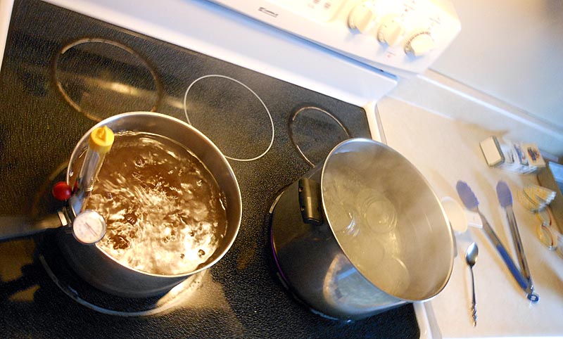
Finishing the maple syrup boiling process on the kitchen stove

After the bulk of the boiling was done outside I did the finishing and canning of my New Hampshire Maple Syrup in the kitchen.   I need to get a hydrometer and a better thermometer for next year.  I learned from my first batch of boiling that it is easy to over boil.   Over boiling results in sugar crystallizing and precipitating  from the syrup as “sugar sand” as your syrup cools.

I need an assistant for the canning process next year.   I will have to enlist the aid of a friend and bribe them with a jar or two of precious syrup.  It was quite hard to juggle everything during the canning process solo.   I used coffee filters in a little filter jig over each jar for filling.    Coffee filters have a very fine a pore size and blocked up rather quickly.  Coffee filters are cheap thankfully as I had to use a new filter for each jar I filled as the pores blocked up.  The smell of the boiling syrup fills the house with a wonderful warm aroma that lingers for the entire day.  I quite enjoyed the scent of maple syrup filling the house.


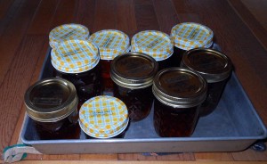
The first go around of boiling produced 25 oz of syrup from ~18 gallons of maple sap.   There were losses in the forms of minor spillage, sampling during process, filtering, etc.  I over boiled my first round and a large amount of sugar sand precipitated from it as it cooled.  My first round was capped with aluminum foil and put in the fridge for current use.  The second round of boiling I canned in small 4 and 8 oz jars for storage.  Before any friends and family ask, no there is none left for the asking this year.

first breakfast with home made New Hampshire Maple Syrup

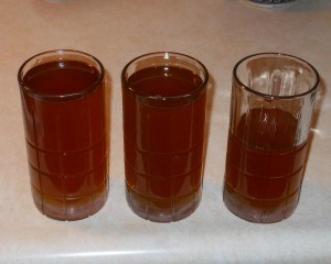
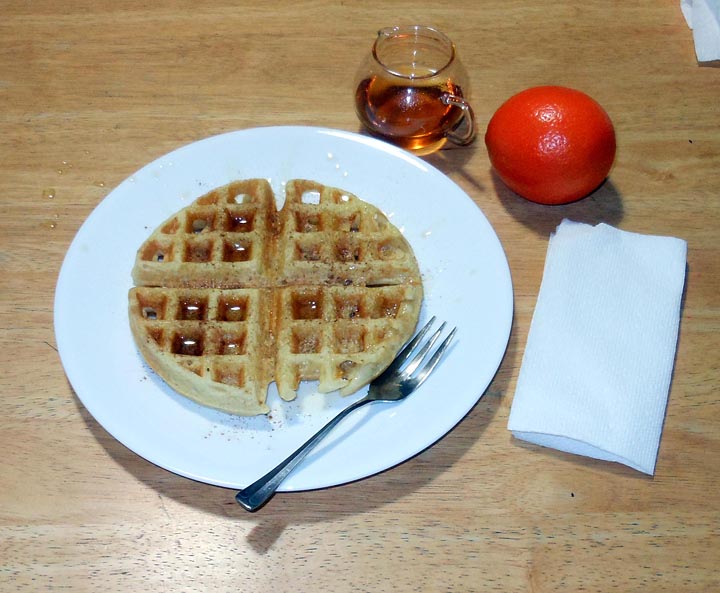
This is my first meal I enjoyed with Zac’s New Hampshire Maple Syrup.  It was delicious.  The first run of syrup was very light and super sweet.  It was not strongly maple flavored but very enjoyable.  I have since enjoyed a breakfast that uses maple syrup on most mornings.   Food you grow or acquire yourself always tastes better and I can now say this holds doubly true for Maple Syrup you make yourself.

I’m certain I will do this again next year and suspect I will be a fair bit more serious about it.  I might build a small reverse osmosis unit using commonly available household cartridges to concentrate the sugars before boiling.  I will get some 55 gallon food grade barrels for sap storage as the 5 gallon pails are too small and you need too many of them.  I must come up with a better wood fired evaporator solution, either by building an arch from scratch or modifying my current wood cook-stove.

Ballscrew upgrade on RF45 – ZAY7045 Milling machine – Part 2

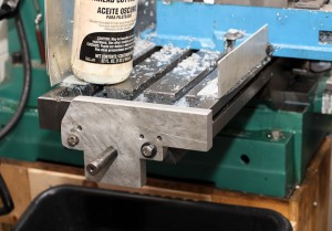
RF45 CNC machine x axis mechanism

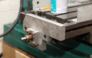
This post continues from an early post, antibacklash ballscrew upgrade on RF45 ZAY7045 Milling machine – Part 1.  After mounting the anti-backlash ballscrew and assuring that it was as square to the table travel as I could get it, I worked on installing the end plates and then the captive support bearings a single 5202 and a single 6202 sealed Nachi bearing.

   Anti Backlash ballscrew upgrade for CNC miling machine

I cut out rough profiles of the endplates on the band saw from some 3/4″ 6061 aluminum stock I had on hand.  I used the original endplates as rough guides.   I did not machine the outer profile very carefully as I felt it was not important enough to justify the time.  I rough drilled the center hole, then marked the actual center by tracing the leadscrew.  A large endmill centered over the markings bored out the ballscrew opening.  This easily lined up the screw in the hole through the support piece.  I liked the idea of using dowel pins to maintain a fixed alignment of the end plates.  Transferring the dowel pins from the original  plates worked poorly so I  drilled and reamed new ones with over under reamers.


After mounting both end plates I focused on the stepper driven side as it would support the leadscrew in both an axial and radial fashion by using a 5202 double row angular contact bearing.   This end is critical as the 5202 bearing is designed to take the axial thrust loads during the operation of the cnc milling machine resulting in no backlash when changing directions.  I needed to machine a spacer for the 15 x 1.0mm bearing nut to tighten my anti-backlash ballscrew onto the 5202 bearing.  I also machined the bearing retention block.  This is just a 3/4″ thick aluminum square faced and bored to accept the 5202 bearing with 10-15 thousandths of the bearing sticking out.  The bore is machined 10 to 15 thousandths shallow so that when tightened down against the end plate the bearing will be held captive with no play in the axial direction.   Drilling and taping the bearing retaining block  in place was done very carefully by clamping down the table,  tightening the bearing hard against the end plate by turning the leadscrew, and carefully transferring, drilling, and tapping the 6mm threaded holes.   This way I was able to use the leadscrew to provide proper alignment of the bearing support block.  It required some careful hand work, but worked well in the end.

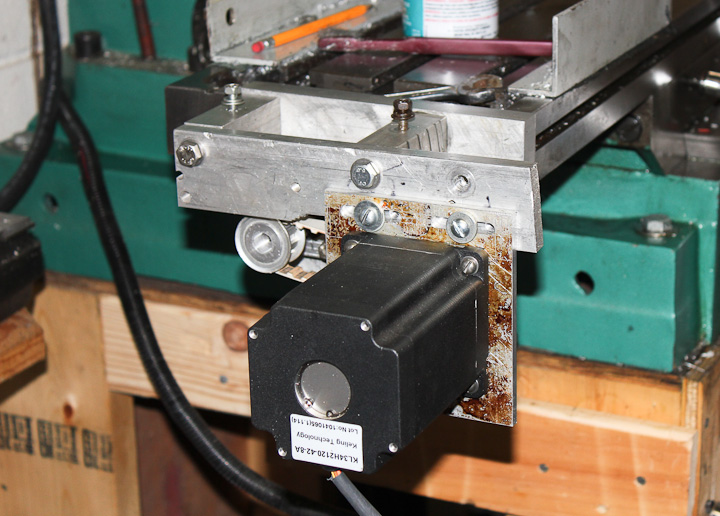
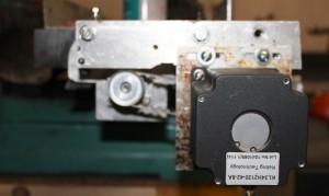
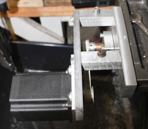
Anti Backlash ballscrew upgrade for CNC miling machine    Stepper drive mechanism with L series timing belt pulleys

As this is CNC machine version 2.0  I decided to reuse much of my original mounting mechanism for the motor.  Originally I had relied on a clamp on mount from the original x axis drive that came with the ZAY7045 mill drill from lathemaster.com.   Version 2.0 would mount off of the end plate allowing me to sell the x axis drive motor and clear up much needed shelf space in the shop .   I am using L series timing belts tensioned by a slotted slide mechanism.   Another change from version 1.2  include a reduction in pulley ratio from 1:2 to 1:1 using 10 tooth L series timing pulleys (part number A 6A 4-10DF05016) from Stock Drive Products/Sterling Instrument  allowing for much higher rapid traverse speeds.  I did have to open up the bore on the pulley to 15mm from the 0.500″ inch stock bore.

With this new ball screw the machine can move the x axis at speeds in the 30 ipm range as an upper limit.  The earlier version  had a max travel speed of only 8 IPM.  Mostly due to the motors not being able to drive the poor quality inefficient ACME leadscrew.  I plan to alter my motor configuration in the future to a direct drive set up with the motor coupled to the ballscrew via a zero backlash misalignment bushing.

Ballscrew replacement on RF45 clone CNC conversion   Anti Backlash ballscrew upgrade for CNC miling machine

The last addition to the drive mechanism is a splash shield.  I use a flood coolant system for CNC milling, making a splash shield for the drive mechanism a must.  I bent and hammered out some 0.095″ Al sheet I had handy such that all of the edges are raised except where it floods back into the milling machine table resevoir.

My work is not done on this project but this post is for now. I carefully measured the other end of the antibacklash ballscrew.  I need to have the 15mm diameter bearing area of the screw (upper right photo at the end of the screw) extended to a length 77mm from this end of the ballscrew.  This is required to mount the other support bearing (6202) and the bearing retainer onto the end plate.  This side only supports the ballscrew in the radial direction and is less critical.  I plan to leave the 15mm dia section long so I can later add either a rotary encoder and/or a manual control handle.  In order to machine the leadscrew end I need to dissassemble the entire machine yet again, carefully remove the ball nut, and find someone with a lathe who is kind enough to help me out turning it down carefully.  Sadly, my 100 year old lathe is not up to the level of concentrically I need machined.

I have driven and tested this new ballscrew setup and it is vastly superior to the original ACME leadscrew.  Higher speeds will allow for faster machining times, especially on parts that have many non cutting rapid moves, such as drilling bolt patterns.  I realize now that I should have replaced the leadscrews years ago and that I now must do the Y axis.  Likely I will measure and get started on the Y axis upgrade when I disassemble and have the x axis anti-backlash ballscrew end machined.  I hope my work helps someone with their own conversion.  I looked hard to find details on what screw would fit, where to buy one, etc. without much success.

An easy childsafe finish for wooden toys

Kid safe non toxic furniture finish

Woodworking projects for kids are a frequent item in my shop.  One of the challenges, especially on wooden toys for babies and toddlers, is how to finish and protect the wooden toy in a safe non-toxic manner.   A classic kid safe wood finish consists of mixing beeswax into mineral oil.  Both of the “ingredients” are safe and non toxic so if the little ones chew or teethe on their wooden toy there is no need to be concerned for their health.  This makes it the ideal kid safe wood finish.

Safe non-toxic furniture finish for wood working projects   Woodworking finish that is non-toxic and kid safe

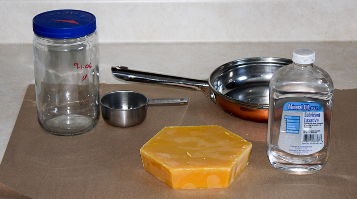
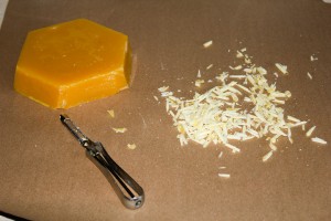
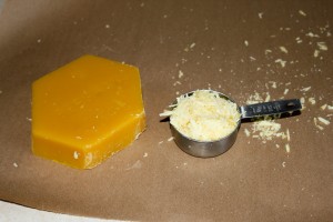
The first step to make our safe non-toxic wood finish is to finely shave some of a beeswax block. Beeswax is not as common as it once was in local stores. I order mine as I use it often for woodworking but small 1oz packages are available at Ace Hardware stores still.  I shave the beeswax on a piece of kraft paper to help contain the sticky wax shavings.  This makes clean up after the project easier.   Into a single pint of mineral oil (available at most pharmacies) add a well packed slightly heaping one half cup of beeswax shavings.

safe nontoxic Woodworking finish    Beeswax and mineral oil finish for wooden toys

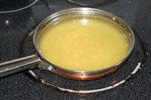
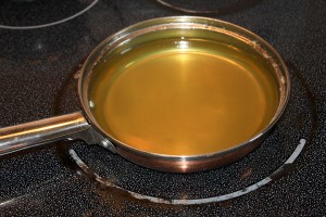
The next step in making the non-toxic wood finish is to pour the pint of mineral oil into a pan.  I have some heavy gauge stainless pans purchased at a yardsale that I use for project “cooking”.    Then add the packed half cup of beeswax shavings.  Using the low setting on your cooktop, slowly heat up the mixture.  Be sure to stir constantly.  It should looks like the left upper photo after you mix in your beeswax shavings.  As soon as the wax is completely dissolved remove your mixture from heat.  The solution of wax in mineral oil turns clear as in the upper right photo when it is time to remove from the heat.  You do not want to add more heat then it takes to melt all of your beeswax into the oil.

Beeswax and mineral oil finish for wooden toys      Child safe woodworking finish on baby toy

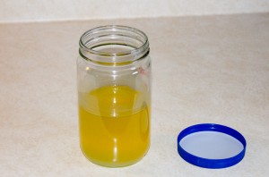
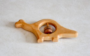
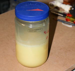
To store your child safe non-toxic wood finish, pour it while still warm into a large glass jar.   You can use the finish immediately as a warm liquid, but as it cools it turns into a soft brushable paste.   Application is very easy. Simply brush on  a liberal coating to your wood project and let the finish soak into the wood for 10 minutes.  Then buff with soft cotton cloth to remove any excess finish.  The little baby rattle toy was the purpose behind this batch of kidsafe wood finish.  The little dinosaur baby rattle is available at my etsy shop for purchase along with a fish rattle and flower rattle.   They have been kid tested and mother approved.

childsafe non toxic wood finish for wooden toys

The cooled finish is a soft brush-able paste.  If you leave it in a sunny window on a warm day it will liquify again if you prefer to use it that way.  I’ve found no discernible difference between using it as a paste or a liquid on wooden toys.  I like to let this finish sit on the toy for at least 24 hours before I buff it out to a soft natural look while removing any excess with a soft cotton cloth.