How to make a drill press spindle lock clamp


Drill press spindle lock assembly


It has been some time since my last post.  Summer is the time for swimming, sunshine, adventures, friends, fishing, and so on.  All of that has been keeping me pretty busy these days.  Here’s a post on a recent project to keep you entertained. I needed a spindle locking mechanism for my large drill press to help me convert it into a wood branding press.  The nice thing about having the  CNC milling machine I built for myself is that when I need a part or machine I can readily make it. It’s hard to imagine how I survived in the days before having CNC machining in the shop.

There was no built in spindle locking mechanism for my industrial drill press, and no add-on accessory available for purchase to lock the spindle.  I decided to take action and design my own add on mechanism.  I feel the best way to lock the spindle was to clamp the lower spindle were the Morse Taper socket is located on the bottom of the spindle (shown in the photo above).  I originally toyed with a removable pin mechanism in the spindle itself, or clamping the belts up top somehow.  Both of those ideas seemed more difficult then the solution I will share in this post.


I started with a piece of half inch aluminum stock.  This was an old adapter plate from some work years ago.  As such it had a few holes in it.  I carefully selected the origin of my part such that the machining would remove the material where the existing holes were located.  This careful setup up allows me to reuse scrap stock or old material from previous projects.   The next set of photos are just time lapse photos of the machining for your oogling pleasure, as such I will not comment much on them.


As you can see the finished part was milled out of the aluminum stock.  The only real downside to machining parts this way is at the end you are left with a small very sharp triangular nub on wherever the cutter started out.  I simply file this material off by hand.  For more exacting machining work, I would have made a jig by drilling and taping mounting bosses inside the part somewhere, this way the profile would be machined completely, resulting in a higher quality machined part.

The part took 30 minutes to machine. I might have been able to push up the machining speeds but I’m reluctant to push the speed as I do not want to break my end mill. This was my first part cut with the new HSMworks software I installed thanks to learning about the free version from Jim Wilkinson on Facebook a while back when he saw a previous project post.  Thanks Jim!


The next step after the CNC milling of the drill press spindle lock’s body was to drill and tap a single clamping screw. I used a 1/4″ – 20  tpi tap.  I tend to use quarter twenty bolts for just about everything not load critical in my designs as I stock a large variety of bolts in that size in my shop.  Simplifying your designs by using only a few standard threads for all of your projects is a good idea for hobby projects where weight is not a concern.

Above you see the more or less finished spindle lock assembly in place. I had to take the left side depth guage/stop assembly off, but as this is only a single nut it takes less then five minutes to put on the spindle clamp.  I cut the slot out in the wood shop on a miter saw with a thin kerf carbide tipped blade.  I could have milled it but it is very fast to use a saw blade for slitting operations.  The only thing missing from this picture is a spacer to clamp down on and lock everything tightly in place.

Above you see the finished spindle lock assembly.  I quickly turned down a bit of 1″ aluminum round and made a spacer of the right size.  She’s all clamped down and I am now ready to do some wood burning with our new electric branding iron.

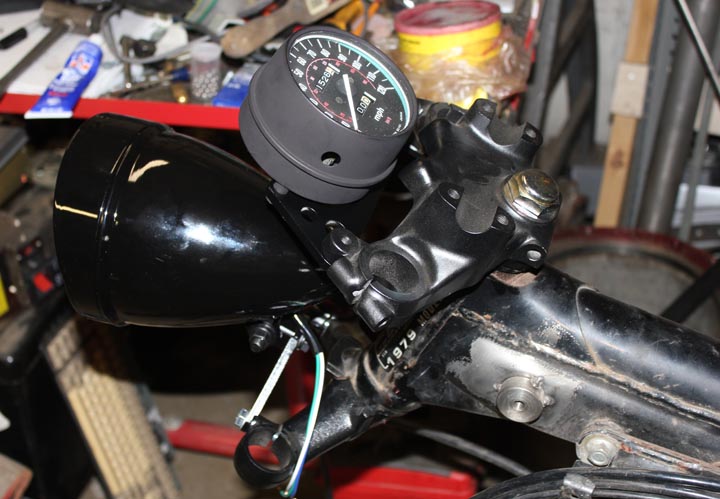
I hope to be more active in posting both here on projectsbyzac.com  and photosbyzac.com in the fall.  August is chock full of good stuff and will likely keep me too busy for regular weekly posts.  But stay tuned in the fall, the 3D printer project will be finished before christmas (personal goal).  There will be lots of posts on that as well as continued upgrades on the CNC milling machine and the completion of the Cafe Racer Honda CX500 motorcycle.


New wooden toys in the Etsy shop, including a VW Bug inspired wooden car

Volkswagen Beetle inspired wooden toy car

I’ve put up a few new wooden toys in my Etsy shop.  Check them out, and keep them in mind as a gift for the next little one to join your or a friends family.  The two new featured toys are a wooden kitty cat baby rattle, adding one more to the baby rattles that are selling well, and a wooden car inspired by the classic VW Bug.  Both these toys were inspired by little ones in my life.

Volkswagen Beetle inspired toy car    Volkswagen Beetle toy car

    I was inspired to make this wooden toy car design based on the classic Volkswagen Bug automobile. One of my half dozen godchildren was in love with Volkswagen Beetles after watching the classic movie Herbie and the Love Bug. He would point out every new and old VW Bug he’d see, yelling out “HERBIE!” The wood used to make this wooden toy car is black walnut and has a nice rich dark color. This cute little wooden toy car is sized (6inches long by approximately 2.5 inches tall) only slightly larger then my baby rattles. This toy is designed for children of ages 9 months to 2 years.  As with all of my wooden toys for children, it is finished in a non toxic mineral oil and beeswax finish that is child safe.  If you would like to buy one of these they are available for purchase here on my etsy page.


Kitty cat baby toy   Kitty cat baby toy and rattle

   This cat baby rattle design came about when two very dear friends shared the good news that they were expecting a little one by asking me to make them a kitty cat baby rattle. My wooden baby rattles are sized perfectly for a baby to grab, rattle, and play. I make these wooden baby rattles from maple and oak. I use a safe non-toxic natural beeswax and mineral oil finish so baby can safely play with and teeth on them without concern. They have been kid tested and mother approved.  If you’d like to buy one it is available here on my etsy shop.

Making sawhorse canoe stands

I was in need of some sawhorses to store my canoe (see my previous post on how to make a wooden canoe yoke), and my fishing buddy needed a set for his canoe at the new apartment he moved into recently.   One of my first logs cut up with the Alaskan saw mill I made for my chainsaw was already chewed up by insects.  There were beetle holes throughout the log and as such the boards were not really good for any sort of finished furniture project.  I decided they would be the perfect boards for making a couple of sets of sawhorses to sit outside act as canoe stands.  I also plan to use my set for milling logs into lumber.

rough sawn boards from alaskan sawmillThese three boards are what I used.  The two smaller boards made 2 sets of legs. The thick center board (3.5″ slab) I used to make the tops of the sawhorses.  It is certainly possible to build similar sawhorses with purchased lumber.  I will put up a drawing later when I have time with plans for 2 by construction of these simple  but sturdy sawhorses.

   Sawhorse top board milled with 15 degree angles

I used my thickness planer to turn the thick slab into 3″ thick dimensioned lumber.  I then ripped the boards with a ripping blade on the table saw.  I used a 15 degree angle on the legs.  I have found that legs splayed at 15 degrees work very well to make for a sturdy support on a table or sawhorse.

how to make a Canoe stand - top boards    sawhorse legs with 15 degree mitre cuts top and bottom

After cutting the top boards, which are in fact the main structure of this simple sawhorse design, I used the planer to make all of the surfaces straight and at the appropriate angles.  I cut the tops to 39 and 38.5″ wide for each pair.  The shorter sawhorse will easily stack underneath the longer one.  If you make them the same length you can have issues with the anti splay bracing on the legs interfering. I cut each set of legs at one time using the first piece as the template.  I made the legs 31″ long and the ends are cut at 15 degrees to match the angle of the legs.  Each leg was cut and planed down to 1.25″ x 4.5″ dimensions from the rough lumber.

first screwed together sawhorse    Simple sawhorse design for storing canoes

The legs were each screwed on to the top board with four 2.5″ long stainless steel deck screws.  Since the wood was free, I decided to splurge and use good stainless steel screws to hold the sawhorses together.  After all they will spend the majority of their time outside with a canoe on top of them. I would hate for them to rust away to nothing and find my canoe broken from the fall one morning years from now.

Sturdier sawhorse design for alaskan saw milling logs into lumber

This is the second set of legs that I made a bit sturdier by the addition of the cross bracing.  I put one set of bracing inside the leg, and the other outside so the two sawhorses can stack for storage if I am not using them to hold my canoe or for Alaskan chainsaw milling of logs .   I’ll take a pic of the canoe on the stands, as well as put up some drawings of the sawhorse designs in the near future.

Stacking sawhorse plans   

The finished sawhorses / canoe stands got some pressure treated feet.  Icut up some left over scrap pressure treated 5/4″ decking boards into feet for the sawhorses.  I attached them with a couple stainless steel deck screws.  This should extend the life of the pine sawhorses considerably by keeping the less rot resistant pine legs off of the ground and dry.

How to CNC machine a part from start to finish

Several readers have asked me for a post explaining the entire part creation process starting with a part concept, going through fabrication and ending with the part in use.   I use a ZAY7045 (RF45 clone)   Milling machine that I converted to CNC  to make parts for my projects.  In this post I will be sharing the details on the CAD design of parts, CNC coding, and fabrication process.   I will be using a two different pieces ( a headlight mounting bracket  and a speedometer mounting bracket) I made recently for my Honda CX500 Cafe Racer build to illustrate and outline the basic process of CNC fabrication of custom components.   I will keep the details simple such that everyone can understand how the CNC fabrication process works.

Speedometer mounting on a CX500 Cafe Racer

All parts start with a need,  in the photo above,  I need a bracket to locate and mount a single gauge to the upper triple clamp on my Cafe Racer Motorcycle Project.   I start by holding the speedometer gauge in place and taking some measurements.  It’s critical to carefully measure details like mounting bolt hole spacing.   As a rule of thumb I measure the smaller and larger dimension and take the midpoint between those numbers.    Here’s a Zac Shop Tip:  if you measure and calculate 138.43 mm,  it is very likely the actual value is the next nearest whole or half number,  ie. 138.5mm. After writing down the measured values on a small notepad, I next go to the computer to draw up the part.

Cad drawing of cnc machined part with different layers for different operations

After careful measurement, it is time to draw up your part in a CAD software package.  I’m quite fond of Dassault Systems, Draftsight software for generating simple DXF and DWG drawing files.  I am familiar and proficient with Solidworks, a 3d design software package which makes using the free Draftsight .dwg/.dxf CAD software an easy experience.  The above screen shot shows my version 2.0 headlight mounting bracket as drawn in draftsight.  You can see the part layer in white, the cutting layer in magenta, and the milling layer in green.  I manually set cutter offset in my drawings (a topic for another more technical post).  Each layer will have a different code generation step in the next part of the process.  Separating them out here makes life easier later on when generating the G-code for the CNC Milling Machine.

The CNC code generation software I use is not great, but I can not afford very expensive enterprise level software for this stage and thus I make do with what I have available.  I use this software to put the basic building blocks of the code in place.  I then rearrange, and edit the Gcode (CNC Machining programming language) into a form that is more usable and efficient.  The above photo shows a screen shot of the step in the process where I can set individual layer settings for the cutter.  You may recall I explained the need to generate separate layers earlier in the post and this is the purpose.  If you do not separate operations into layers you end up having to do a lot of tedious manual editing of your CNC Gcode program.

CNC Gcode generation

After chaining the layers together, so that the machine can generate code that does an entire loop in one go vs each individual drawing item  one at a time,  the software generates a basic G-code program.  I then carefully reorganize, and edit the code to make the program safe, do what I want, and in most cases more efficient.  The software tends to break things down such that the machine spends a lot of time traveling between points of entry into the material.  I reorganize the code snippets to minimize this which in turns shortens the machining time considerably.

The above photo, is the Gcode generation for the v1.0 headlight mounting bracket.  I made this first part as a fast test of the mounting location and strength of the 1/4″ thick 6061 aluminum plate I would be making this part from.  I will use this part in the next couple pictures vs the V2.0 headlight mounting bracket we’ve seen in the post so far.  I did not plan to put this post together ahead of time and missed some pics in the process with the v2.0 mount.   Rather then wait till I build the next part, I wanted to get this up to help my readers understand the process as soon as possible.

CNC machine software controlling the milling of a part   

Above you see a screen shot of the CNC machine control software running the machining process.  After lots of careful checking and setting a zero point on a larger piece of metal “stock” clamped into the machine I start the program and the machine does the rest.   This is really fantastic when you are making 4 of one part as after the first time the code has run through and is validated I will start the program and leave to do other tasks in the shop.  My CNC machine is not 100% self sufficient yet, so I periodically monitor it when it runs.  The number one problem with my current set up is coolant spraying everywhere making a real mess.  I plan to place the machine in a full enclosure at some future time.

CX500 cafe racer headlight mount Ver 1.0

The above photo shows the cafe racer headlight mount version 1.0 in place on the bike.   While this was a functional part, I learned I needed three changes for version 2.0.  The first change is that version 2.0  needed to be less ugly.  Aesthetics are important on some projects, and my Cafe Racer is to  be a thing of beauty.   Secondly I learned that I wanted to raise the headlight another inch or so in version 2.0.  Third I needed a slot to keep the headlamp from rotating, especially important to prevent it rotating with riding vibrations over time.

    CX500 Cafe Racer custom CNC fabrication

Above you can see the version 1.0 and version 2.0 parts together.  Clearly version 2.0 is superior in every way.

Custom CNC cafe racer parts built to orderAbove is the finished and painted bracket with the headlight mounted on the bike.   I am quite happy with the way it came out in the end.

     CX 500 cafe racer CNC fabrication

Similar to the headlight mounting bracket, I generated the code for the gauge mounting bracket for the speedometer.  This program required considerably more reorganization of the code to make run efficiently.  I use a simulation to determine the program run time.  The “as generated”  Gcode had a run time of almost 45 minutes.  I managed to get that down to 28 minutes by manually editing and reorganizing the G-code in the program.

CX500 Cafe Racer parts made to order   

Now for a bit on post CNC machine processing of parts.   I start by deburring all of the edges with either a deburring tool, a fine file, or sandpaper.   The machining process often leaves razor sharp burrs on the edges where it cuts the metal. The  parts used as examples in this post were primarily deburred with sandpaper.  I then wash them with warm soapy water to remove any cutting oils and coolant left on the part.  A quick trip to the sandblasting cabinet and they are left with a fine surface finish ready for paint.  Another trip to the shop sink to wash off any residue sand from the blast cabinet and they are ready for painting.

I often paint small parts like these brackets hanging from bits of bent copper wire through a bolt hole.    Several light coats of a quality paint results in a hard durable finish.  A hairdrier (buy one especially for this purpose, do not “borrow” your significant others for painting car parts) can be used to help flash dry the paint between coats, or in the winter time cure the paint quickly in colder temperatures.

Cafe racer guage mount speedometer

Here’s the finished CNC machined bracket on the bike.

Cafe Racer Speedometer  CX500

    I am very happy with the way these parts came out and the overall look on the bike as this project progresses.  If you want more information on these parts (drawings, etc)  or would like me to make one of these parts for your CX500 motorcycle project,  leave a comment on this post or email me at zac at projectsbyzac.com.  I hope this helps my readers understand the process of how to make parts with a CNC machine.  When I finish my 3d printer project I will do a similar post on 3d printing parts from start to finish.

I’ve gotten a number of requests for the drawings I used to make these parts. Here are the DXF files I used to mill each of these brackets, this was before I had real cam software so they are ofset by 0.125 for G-Code generation via very primitive software.   I had to convert the DXF to PDFs to share them with you in wordpress.  It claims DXF is a security risk.  You can convert back or open them in your cad software and everything should still be ok.  CX500 front light mount   &    cx500 guage mount