Category Archives: Tool builds improvements and repairs

Upgrading shop lights with 12V DC LEDs using 3528/5050/5630 Flexible Light Strips


Shop light using 12V DC LEDs using 3528/5050/5630 Flexible Light Strips   We all have them in our workshops, the cheap dual 48″ fluorescent tube shop lamps or “shop-lite”.  The negatives of these low cost lamps being winter temperatures making them either not start, or flicker like crazy.   I decided to try an upgrade using 12V DC LEDs using 3528/5050/5630 Flexible Light Strips.  LED’s start instantly, don’t flicker even at very low temps, and my shop light conversion to LED’s decreases the energy consumed to about 20% that of the fluorescent tubes making it an environmentally beneficial green upgrade.

12V DC LEDs using 3528/5050/5630 Flexible Light Strips    12V DC LEDs using 3528/5050/5630 Flexible Light Strips

   Originally inspired by the number of dead tubes and starting ballasts in many of my shop lights I went to my local Home Depot and Lowes to look at replacing and repairing these lights.  However the price of both the tubes and shop lights has increased greatly since I last purchased some.  Additionally there’s a buck a tube fee to dispose of the tubes now.  I decided I could do it cheaper and better with LED lighting, but once again the ones I could purchase were quite pricey at ~$40 a piece.   I had used some of the 3528 led light strip (about $6 for 5 meters) inside my 3D printer enclosure in the past and it worked amazingly well.  I also have a plethora of free 12V dc power supplies in my parts bins making a light conversion to LED cost me about $3.  Seemed like a win win situation, I’d use up some parts on my shelves, save money, and make a lamp that was considerably greener then the fluorescentversion making me feel better about my lowered impact on the environment.

12V DC LEDs using 3528/5050/5630 Flexible Light Strips     12V DC LEDs using 3528/5050/5630 Flexible Light Strips

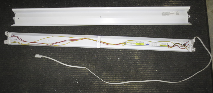
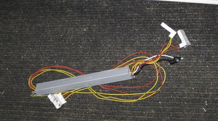
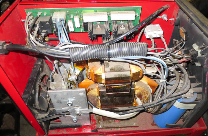
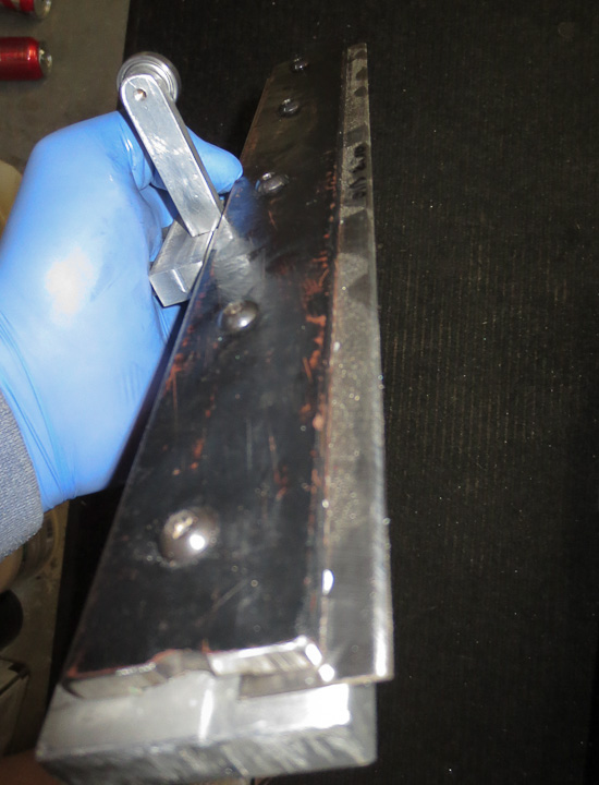
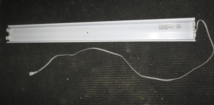
   A pretty easy project, it starts with disassembling the old light and removing the internal electronics.  Open up the light, pull out the parts, and remove them from the lamp.  This is one of the better shop lites I have. It has an actual electronic ballast unit, and it still worked so I removed it carefully and am saving it for a future project or repair.  Some of these lights have really bad, poorly made ballast set ups that are scary when you see how unsafe the design is inside.

Shop light with 12V DC LEDs using 3528/5050/5630 Flexible Light Strips     Shop light using 12V DC LEDs using 3528/5050/5630 Flexible Light Strips

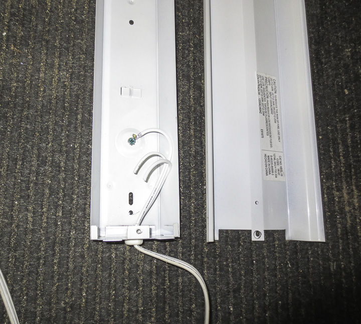
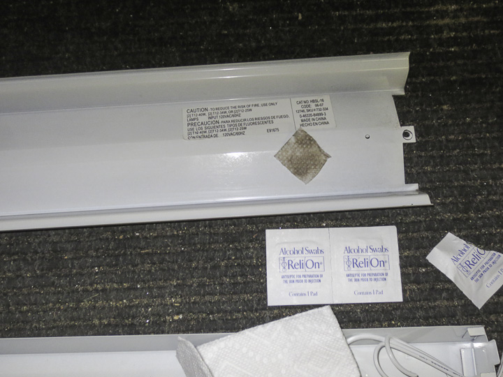
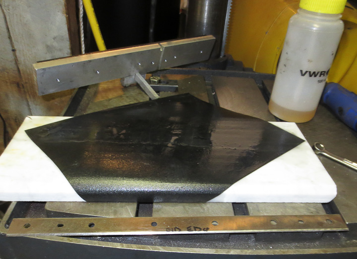
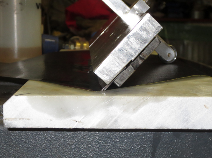
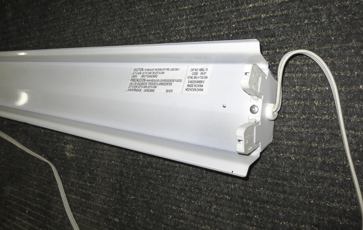
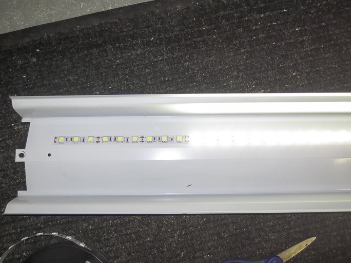
  We are just using the body or sheet metal “shell” for our light conversion.  I like the shop light look, and the sheet metal has angles that will help spread out the LED lighting, which radiates out at a fixed angle from a point source rather then in a full 360 degrees like the tube.   Make sure you clean the metal well. Even after using some Lysol scrubbing wipes to clean them, I found an alcohol wipe still removed some grease from the surfaces.  We want the 3M adhesive to have an oil free clean surface with which to bond when we apply our light strips to the frame.

Shop light using 12V DC LEDs using 3528/5050/5630 Flexible Light Strips

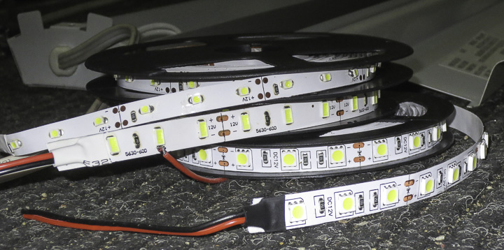
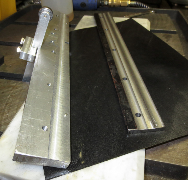
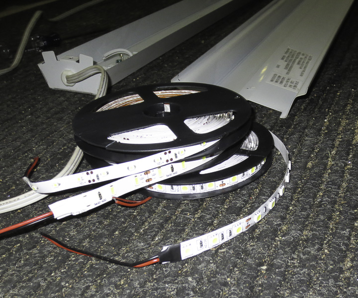
   There are three common varieties of these LED light strips available at low cost on Ebay and other supply websites.  They come in adhesive strip using 3528/5050/5630 LEDS.  Additionally you can buy them in waterproof sealed strips for additional cost but I did not need them to be sealed.  Above you see one 5 meter roll of each strip. They are very easy to work with. you cut them to length where you see the two copper tabs.  Then you can easily solder strips together by connecting the end copper solder tabs.  The different numbers refer to the actual dimensions of the LEDs. I’ll do a second post on  what the differences are, as well as an evaluation of which one makes for the best shop light.

Shop light using 12V DC LEDs using 3528/5050/5630 Flexible Light Strips

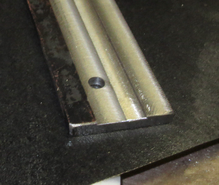
Application of the LED light strips to the shop lamp is very easy.  Simply cut to length, being careful to cut in the middle of the small copper solder tab space.  They have a cutting line for you to follow (you can see it on the left side of the right image below).  Remove the adhesive backing strip and carefully place it onto your lamp.  Be careful, the LED’s themselves are sharp, I use a bit of cloth folded up to apply pressure to the strip as I stick it down to save my fingers. Start on one end and kinda roll it down onto the metal of the shop light.  Sometimes the copper tape gets kinked a bit from being on the roll.  You want to maximize your adhesion by pulling and rolling out any bubbles or kinks as you work along the length sticking it down from one end to the other.

Shop light using 12V DC LEDs using 3528/5050/5630 Flexible Light Strips    Shop light using 12V DC LEDs using 3528/5050/5630 Flexible Light Strips

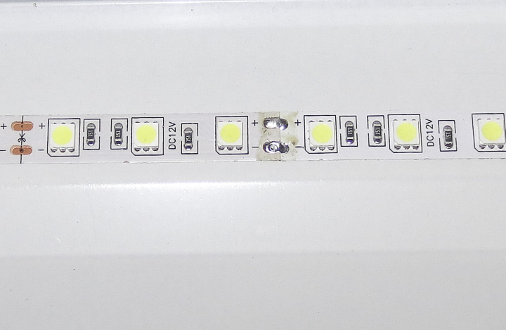
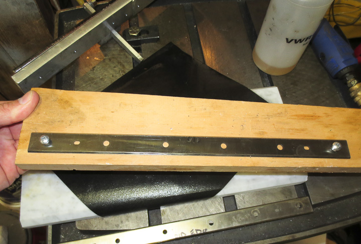
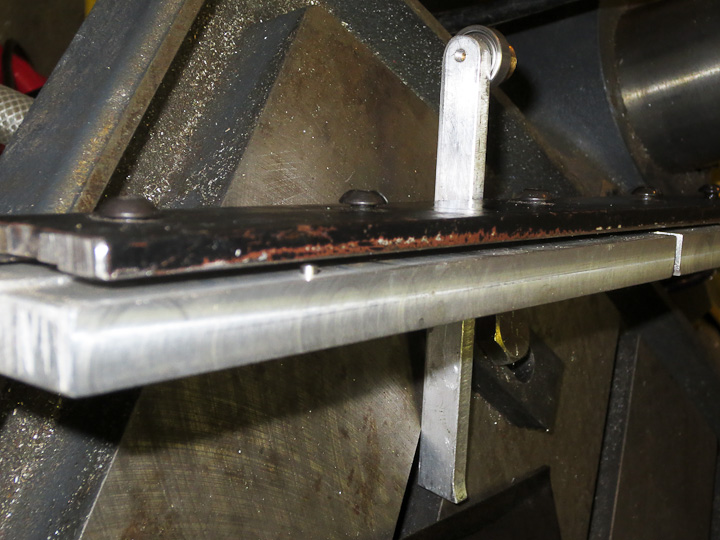
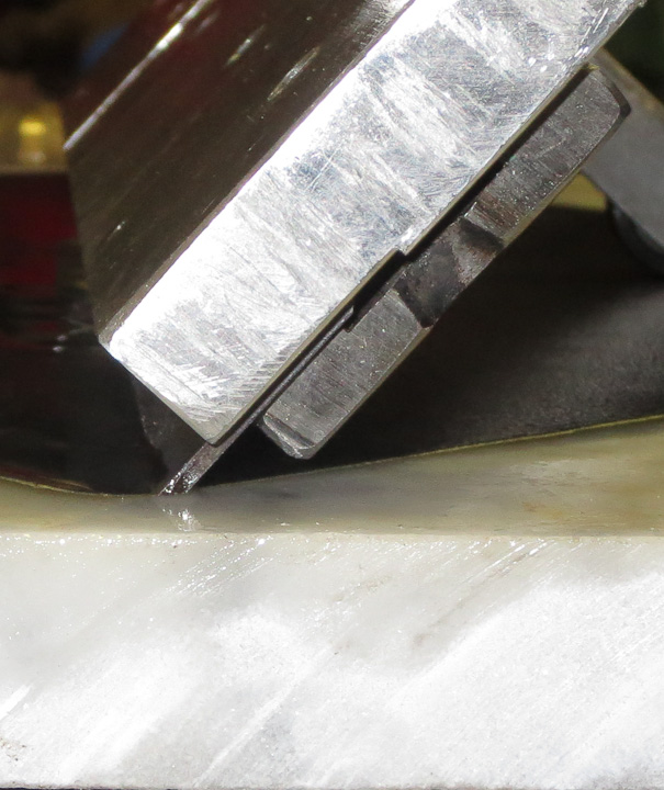
The strips are manufactured in shorter lengths and then soldered together connecting into long lengths.  When I turned this particular section on, as you can see above, it did not light up all everywhere.  The solder joint from manufacture had cracked and broken during the rolling or unrolling.  If this happens, a quick touch up from a hot solder iron to the soldered tab (above right) will reflow the solder restoring a good electrical connection.

LED Light Strip Shop Light-1960

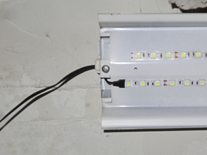
Connect up your 12V power supply.  I’m using the 12V DC 2A kind that come with many electronics. I have a dozen or so in my parts bin.  I pick these up for project use whenever I can.   I did two different methods on my light conversion.  One where I used the original shop light’s power cord. The other where I just directly soldered in the power supply cord to the light.  Both are functionally identical.  I can’t advise you as to which is better.  For my purposes the decision was based on the shape/size of whichever power supply I was using.  If it fit in the shop light body I kept the original cord.  If not, I soldered the power supply wires directly to the strips.

LED Light Strip Shop Light-1959

When soldering the ends together, make sure you keep the + to the + and the negative to the negative.  LED’s are diodes, and as such only flow current in one direction.  If a whole strip isn’t working, likely you have the positive and negative backwards.  I also put some Kapton (polyimide) tape underneath where the strips ended and I soldered. This was to ensure no electrical shorting to the light frame.  You could just as easily use a piece of electrical tape but you want to make sure to add this safety feature to prevent any risk of electrical shock or shorting.

Shop light using 12V DC LEDs using 3528/5050/5630 Flexible Light Strips

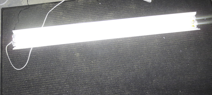
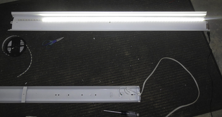
Testing the completed light is easy, plug it in.  These lights are  up in my shop now and working great. I’ll write a second post soon comparing the different LED’s  ie 3528 vs 5050 vs 5630 in this application.  I will share which one I feel is makes the best shop light, as there is a clear and away winner out of these three.  Hope you enjoyed this quick post, learned something, and as always don’t follow online projects verbatim blindly, think, be safe, and be smart when working on your own projects.

Diode replacement on Lincoln Weld-Pak 100 Welder Repair

welder diode replacement     While working on another project, a diode shorted out in my Lincoln Electric Welder,  a Weld-Pak 100.   I needed to replace this diode but finding information online was challenging.  To help others, and myself in the future,  I am sharing data and specs for the replacement parts I ordered to fix my Lincoln Welder.   I knew the issue was a diode and not a transformer short because it still  made an arc (very poorly), but became a buzz box with the right sound without throwing the internal breaker.  A short in the transformer would likely trip the breaker quickly and not continue to generate an arc.    Opening up the weld-pak 100 and testing the diodes with my digital multimeter with it’s diode setting quickly identified the problem diode.  To do this you have to first remove the diodes from the aluminum plate that acts as their heat sink (or at least the output wires from the plates).

****This project, like many projects by Zac is not a task for the unskilled or those lacking knowledge. Electricity is dangerous!  It can and will kill you!***

If you don’t know exactly what you are doing to be safe, do NOT attempt any kind of repair like this.   Always unplug, and check (verify with a meter safely) that any and all capacitors are discharged fully before testing or working on any electronic device.  I’m sharing this info, primarily to have the data easily accessible should I need to replace or repair my welder again in the future.

welder diode replacement

The Lincoln Weld-Pak 100 diode replacement is a huge PITA.  There is not one smidge of extra wire inside to allow things to move freely making it challenging to work on.  In addition, the transformers are made from wide aluminum strips, and it’s pretty much impossible to move this aluminum strip in the wide direction.   The trick I found to getting the diodes out (they are attached to the rectangular aluminum plates on the left bottom of the above photo) is to undo all of the bolts before trying to get at them.

welder diode replacement Removing what passes for the heat sink (aluminum plate pictured above) from the welder is problematic as well.  Working on this welder is not easy because there’s not a lot of wiggle room on any of the wires.  From a design standpoint this makes sense, least amount of wire will result in the lowest losses.   To get the heat sink plates out use a thin screw driver to pry the inside plastic  clamp and pull the plate towards the front and then up.  I broke off one of the little tabs that locks the plate in place due to prying a bit too much. Thankfully there are two on each plate.

welder diode replacement Above is a side by side photo showing the original diode on the left and the replacements I ordered on the right.  The original rectifier diodes used in the bridge rectifier assembly to generate the DC current used for welding are International Rectofier parts:  IR M9661 40RU (reverse configuration) and IR M9661 40U.  There are 4 diodes in total, and 2 of each part number making up the bridge rectifier assembly.  One of mine was blown, being shorted out such that it allowed electricity to flow in both directions.  These diodes are rated at 70A and 300V based on what I could find on the net, in welder forums and user groups.  The original replacement parts are available from Lincoln and welding supply companies for about $24-30 each.   While that is an option, most of the welder forums recommended replacing the diodes with higher voltage ratings as often they blow due to repeated voltage spikes during the welding process.   I decided to replace all 4 o the diodes in my Lincoln Weld-Pak 100 Welder.  I started my search for replacement parts at Digikey.com (my favorite supplier of electronic parts) but they do not stock higher power rectifier diodes.  I ended up finding what I needed at Newark.co. There were lots of options to choose from,  my choice might not be the best one. If you follow in my footsteps understand this fact.   I as not 100% certain the diode replacement would entirely fix my welder, as such I went with the cheap option.  I ordered two Solid State 85HFR120 and two of Solid State 85HF120 diodes from Newark.com with a total cost plus shipping of considerably less then one replacement OEM diode.   These diodes had the same form factor as the originals and are rated at 85 amps forward current and more importantly a much higher repetitive reverse voltage max of 1200V.

welder diode replacement

Above is the wiring diagram for the Lincoln Weld-Pak 100 Welder.  Thankfully it was inside the welder.  When I looked online I couldn’t find a wiring diagram for my Lincoln Electric Welder and thus I’m sharing it here.  Sometimes it is nice to find things like the circuit diagram for your Weld-Pak welder before you open it up.

welder diode replacement

In order to get the second aluminum plate heat sink out from the welder I had to completely remove the fan assembly.  The plates are supported as well as electrically isolated by the fan assembly so be sure to go careful and not break anything.  When you put it back you need to be very careful that everything is floating in air and no uninsulated parts are touching any other metal parts.    This welder uses air gap to electrically isolate some of the components.

*** Special note ***  DO NOT CUT THE WIRES TO THE DIODES!   There is no extra wire, you MUST DE-SOLDER the wires, and then put them through the new diodes for soldering!   Yes this is not easy, but trust me, if you cut them you will not get it back together without having to replace more things and take the entire welder apart.

welder diode replacement

Replacing the Diodes on the Weld-Pak 100 is pretty straight forward in theory.  Desolder the wires from the old parts, solder on to the new ones.  You may have to squish the wires  while hot with needle nose pliers to get them through the new diodes, or wiggle them in while the solder is melted (using tools not fingers, melted solder is hot).  With all of the diodes replaced you are ready to carefully reassemble the diodes and heat sink plates.  I’m not sure one way is easier then the other. I put the aluminum plates mostly in place but not fully.  This way I could wiggle things into place and then tightened down the nuts.   BE SURE TO USE HEAT SINK PASTE ON THE DIODES when mounting to the Aluminum plate.  I did not have torque specs on the diode nuts, I just made them tightly snug.  Enough so I was sure they wouldn’t come loose, but not tight enough to break anything.

welder diode replacement Once you have it all back together, be sure to check that you have nothing touching that is not supposed to be touching. I used a little bit of Kapton film to insulate the transformer “wire” strip on the off chance that something came in contact with it in the future.   I loosely layed the cover back on and did some test welding.  The welder worked marvelously. I suspect perhaps my diode was iffy for a while as I was once again getting that nice sizzle sound from mig welding.  I realized on hearing it I had not heard that sound quite right for some time.   The bead of weld my weldpak 100 layed down was perfect.  I’ve since welded quite a bit with the repaired welder and everything seems to be great having replaced the rectifier diodes on my Lincoln Weld-Pak 100 Welder.

If you found this post useful, let me know, leave a comment. It’s nice to hear someone found my post useful.


Simple Jig for Hand Sharpening Planer Blades

Sharpening planer blades by hand    Every serious woodworker has a thickness planer in their shop.  The best lumber is often sold rough, allowing the craftsman to plane it down to the perfect thickness without having to worry about getting nicks or scratches in the surface while storing/transporting it.  Since I have been milling my own lumber I rarely buy wood but all of my wood needs to be planed smooth to thickness.  This has resulted in significantly more wear on my thickness planer blades and an increase in frequency to my sharpening the planer blades.  To help with the sharpening chore I built a hand sharpening jig out of stock I had in the materials bin using my CNC Milling machine.

13 planer blade sharpening jig-2134    My planer blades are 13.5 inches of double edged sharper then a razor tool steel about 1/8″ thick. I found the best way to handle, move and store them between the planer and sharpening is by attaching them to a bit of scrap wood.  This eliminates any chances of accidental cuts or chipping the cutting edges.   After a couple hundred board feet of lumber goes through the blades need to be honed to allow for perfectly smooth surfaces on the boards.  As the edge dulls or worse gets a nick, it leaves raised marks and imperfections along the length of the lumber as it passes through the thickness planer.  It can be surprisingly hard to remove the marks left on the surface by sanding, making regular sharpening of the blades a must.

Hand sharpening planer blades  The sharpening jig I designed and built is pretty simple. I believe my original idea came from something I saw in Woodsmith or Wood magazine years ago.  In the past, it was reasonable to have my planer blades professionally sharpened (~$15 a pair)  or purchase (~$30 a pair) but today with rising prices (almost 50 bucks for sharpening and 90 for new blades) coupled with the increased frequency I need to sharpen them I can not justify the cost.  The jig consists of a bearing mounted on the end of an adjustable arm that allows for changes in the sharpening angle.  The arm is attached to the body which is essentially a stiff clamp that holds the blades parallel using two dowel pins for alignment.

How to sharpen 13 inch planer blades    13 planer blade sharpening jig-2133

The above left photo shows the clamping piece,  it’s machined flat where it clamps down on the blade.  In addition the center is milled out so all of the clamping force from the machine screws goes onto the center of the blade. This is an important feature.  If you use a piece of unmmachined flat stock you risk having your planer blade rocking or being loose during sharpening.

a simple jig for hand sharpening planer blades

The above close up photo shows the blade clamped in the jig from the end.  You can see the milled slot and how it functions to hold the planer blade completely flat against the other half of the jig.

13 planer blade sharpening jig-2132      13 planer blade sharpening jig-2135

For a sharpening surface I’m using a piece of mirror polished Marble I had left over from some restoration work I helped a friend in Beacon Hill with a couple years ago.  It’s a hard flat surface.  I’m using wet or dry sand paper and emery (for the rougher treatments) to sharpen the blades on the marble slab.  Turned diagonal a standard sheet of sandpaper is wide enough to allow me to sharpen my 13.5″ planer blades.  Use plenty of light oil or WD40 to keep the metal particles from clogging the paper.

How to sharpen 13 inch planer blades     13 planer blade sharpening jig-2137

After careful initial setting of  the angle by adjusting the length of the bearing arm,  sharpening is simply a matter of olling the blade forward and back across the paper with light pressure.  This method takes 10-15 minutes of time  but the results are spectacular.  I usually go from 120 up through 800 grit paper when sharpening my edges.   As I have only used this jig for my longer planer blades to date, after the initial angle setting I have not had to change the angle again and a resharpening goes quickly.  I may make a second smaller unit for sharpening my 6 1/4″ jointer blades in the near future.   This handy little jig cost me nothing, as I made it from materials on hand, and has been used numerous times to quickly sharpen my blades saving me the time and expense of sending them out to be sharpened.

Low cost PID control box for heating/cooling

Assembling a PID temperature control box-1795

One of the joys of the modern world is the availability of low cost PID temperature control modules.  These have been around for a long time in the industrial world but in the past were cost prohibitive for home hobby use.   Now you can buy a pid temperature controller for $25 from Amazon.com.   Adding  in a type K thermo couple ($6),  a 25A SSR ($7) , and some items from your parts bin (switch, outlet, plug, fuse holder) you can build a nice little temperature control panel capable of keeping a piece of production equipment at a fixed temperature while running for less then $50.

Assembling a PID temperature control box-1793   Assembling a PID temperature control box-1792

Only basic instructions are included with the controller, if you aren’t familiar with set up and tuning search the web

This project is more for documentation for future use by myself but here is some back story.  I was in need of a temperature control unit for a piece of production equipment for my company.  We had purchased a cheap control unit that was essentially a solid state pulse width modulator, ie. turning the device on and off  with control of the cycle times.  During production runs the PWM unit did not keep the temperature fixed and we were seeing variations in the final quality of the product.   This is a low risk, non hazardous process and so this quick cheap but very accurate PID temperature controller was the way to go.

***  Disclaimer – I would not use parts of this cost/quality when working on a chemical process or a piece of process equipement where a failure of temperature control would result in something bad happen such as a run away reaction or explosion.  ***

Assembling a PID temperature control box-1787

The wiring is fairly straight forward as shown in my rough, chicken scratches on paper diagram above.  I’m not proud of the drawing, but it was more for the dimensions of the switches then the actual wiring diagram.   I used my cnc machine to mill out the panel that houses all of the components. (dimensioned drawing of panel – PID Temperature Control Panel Drawing)  You could just as easily hand cut openings in a small electronics box if you were building one at home.

Assembling a PID temperature control box-1790   Assembling a PID temperature control box-1791

Be sure to carefully follow hook up instructions on the PID temperature controller.  The unit has makings labeled (Note:  the part numbers in the above picture are for future my reference) on it as well as in the instruction sheets.  These were taken during the first assembly. I have since added a fuse holder between the line in and the switch with an appropriately sized fuse for my device.  Fuses are important as they protect your equipment in the case of a failure.

Assembling a PID temperature control box-1789   Assembling a PID temperature control box-1794

When you wire up projects like this, take time to do a tidy job of it.  While as a hobbiest we do not have 100 colors of wire to choose from, make choices that follow standards if you can.  A few I always keep are white is for neutral and green is for ground in any AC wiring.  Standards are there for a reason. I recently worked on something where the manufacturers chose black wire to be the V+ and green the  V-.  It was nothing but a headache to work on so choose your wire colors appropriately, you might need to go in and add or change something in a few years and keeping to standards makes life easy.

Assembling a PID temperature control box-1788

The finished PID panel works and looks great. It resulted in a significant decrease in reject rate on our production (15rejects/1K reduced to 1 reject/1K). I will build a second identical PID temperature control unit  to run my filament extruder that I am working on building to feed my 3d printer using recycled scrap plastic.