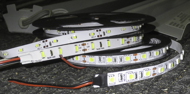
 In an earlier post I shared how I converted shop lights to low cost LED lighting using readily available 12V DC LED light strips with 3528, 5630, and 5050 SMD LEDs as pictured above. These lighting strips are very low cost ($5-8/ 5M roll shipped) and provide an easy way to add light to any place you need it, not just for a shop light conversion. You can run them off an AC to 12V DC power supply or a 12V battery, which makes them extremely handy in the case of a power outage. In this post I compare the differences between each LED strip and share which one makes for the best shop light conversion.

Theoretically the 5630 LED is one and half times brighter than the 5050 LED which is three times brighter than a 3528 LED. However, this does little to tell you which one is really the best light. Interesting is that the part number actually refers to the size of the individual device, with 3528’s being 3.5 x 2.8 mm and so on. All have approximate 120 degree emitting angles, the angle at which the light radiates outward from the chip. You have to be a bit careful with the whole lumens or candela rating on LEDs. These are measured via standards and tell you nothing about the color/quality of the light produced.
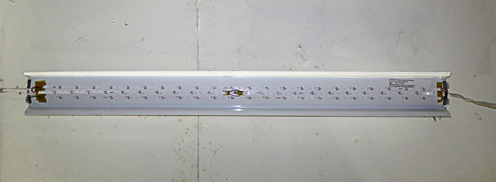
Above shows one of my shop lights converted with 3528 LEDs light strip. I used three lengths of light strip on this lamp. It produces an amount of light that is considerably less then two 48″ T32 bulbs, but is still more then adequate for some shop spaces. The power rate of 0.08W/led for 3528’s makes it the lowest power per LED device of the three. It also has the lowest rated light output. The light output by these strips is a good color. By this I mean observed quality. I am not talking about measured wavelengths. It has a very very slight cool or purple tinge to it, but it is almost unnoticeable. Not noticeable at all without a grey card Kodak photo scale reference handy. For lower power less used areas I think these strips are good. I would not use these in an area I was using all the time as they do not emit enough light. I used these 3528 LED light strips inside my 3d printer enclosure and they work wonderfully for this application. If there’s not enough light you can simply use more of the strips.
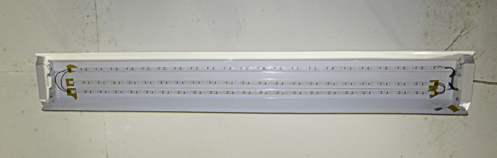 Rated at 0.5W device on strip, the 5640 LED’s are theoretically the “brightest” of the three I’m comparing for shop light use in this post. I find the light emitted from these to be very purple and harsh. I strongly suspect, that the LEDs used in these strips are a low cost clone of the Samsung 5640 OEM chips and thus the poor light quality. This is my least favorite of the lighting strips. I would not recommend the 5640 light strips for any applicaton, the light generated irritates me. Additionally, even with 3 rows (instead of 2 of the 5050 strips) it has less apparent light generated then the 5050 lamp with 2 rows. The real drawback is the color on this one, Have I mentioned that I find it highly irritating? I only converted one lamp to these and I will put it in a location I almost never use because of my dislike of the output lighting. I may even change it over to 5050 strips eventually.
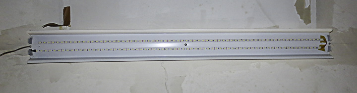 The clear winner of these three and my favorite is the 5050 LED strips. With a power consumption of 0.24W per device, they have a good balance between color output, and total light intensity. Two strips seems more then adequate, vs three of the other strips. I really like the quality of the light produced by these strips. It is a bright white without any weird or subtle tint. It almost feels like natural lighting. These strips are so good I ordered several more rolls of this light strip for the remainder of my shop light conversions as the bulb or ballasts continue to fail.
One last thing to note, the angle of light produced by led strips is 120 degrees. This is different then fluorescent tubes that generate light in 360 degrees. I find these LED conversion shop lights work better in high bay applications then in lower ceiling spaces. the 10 ft ceilings give the light plenty of room to spread out, at 8ft you get a lot less square footage covered by the direct light. I suppose some sort of plastic diffusion panel would help with this somewhat.
As they say, your mileage may vary, but this post aims to share my experience. It may be that the strips I purchased on ebay are to blame for my opinions. If you want to order the same strips I did, here is a link to the ebay listing for strip lights. If the link no longer works, the sellers name is cnredceo. If you search you should find them easily enough. His shipping is very fast, and the packaging is excellent.
** If something should change in 6 months or a year, I will return and edit this post to include any noticed issues or failings.