Category Archives: RepRap 3D Printer

Making a DIY Printed Circuit Board (PCB) vise

Printed Circuit Board holder

I have needed a printed circuit board vise of some sort for a while and have not found a lot of good affordable options that I liked.  I had an old Panavise style hobby vise kicking around the shop for years and I recently decided it was the perfect solution for this project.   I used two different types of 3D printers to make the parts for this project.  My printer, an FDM machine I built myself was used to print up the ABS stronger quick attach mount to attach the vise to my electronics bench.   I used a Formlabs Form1+ SLS 3D Printer to print the PCB holders/grips in a tough 3D printable material that was launched a few months back, appropriately called “Tough”.

 Printed Circuit board Clamping fixtures SLA printed -3321        Printed Circuit board Clamping fixtures SLA printed -3318

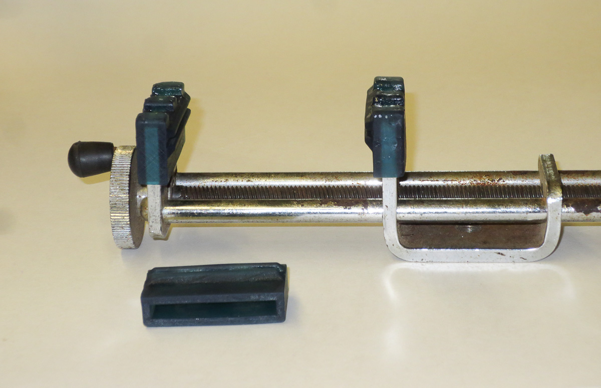
The backbone of this project is an old wide opening Panavise.  These were a staple of the hobby world.  I routinely see them for <$1 at flea markets and yard sales.  I had this one kicking around in my metalworking shop for ages.   I must have  picked up somewhere for $0.25 as it still had the yard sale sticker on it.   These originally came with a variety of low quality rubber “grips” and some sort of mount, often a poor quality plastic suction cup thing meant to quickly attach to your presumably smooth workbench.  I gave away a handful of these to fellow hobbyists a couple years ago but this one survived the culling, and I’m glad it did.

Formlabs Touch SLA Printed grips

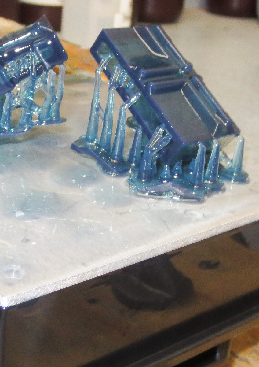
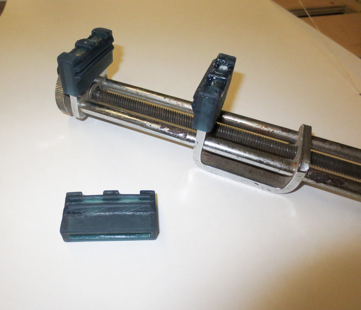
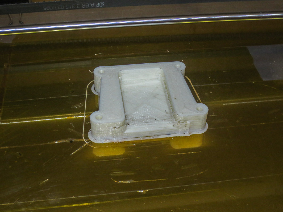
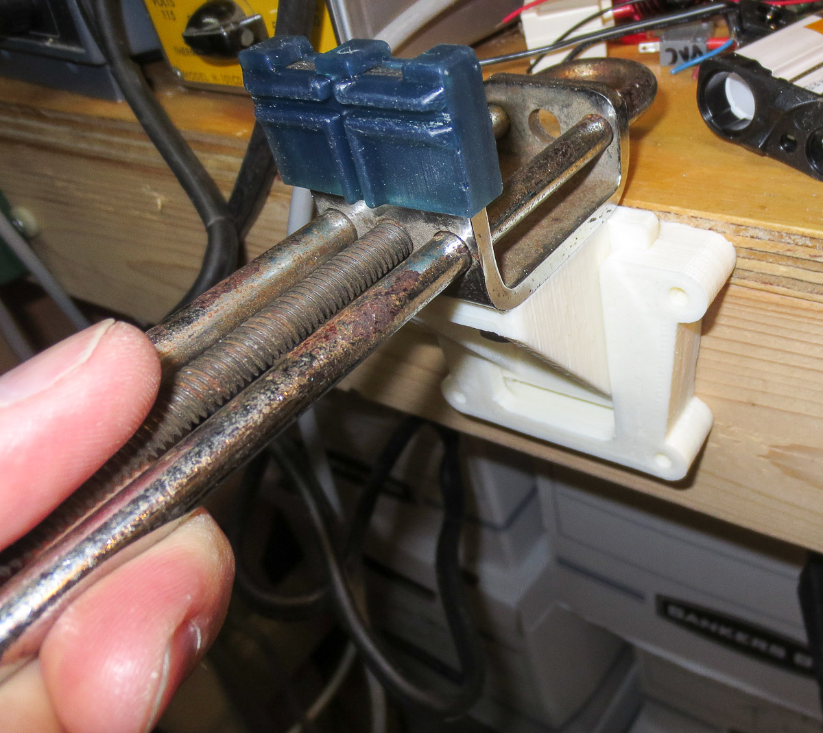
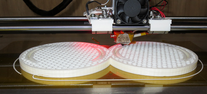
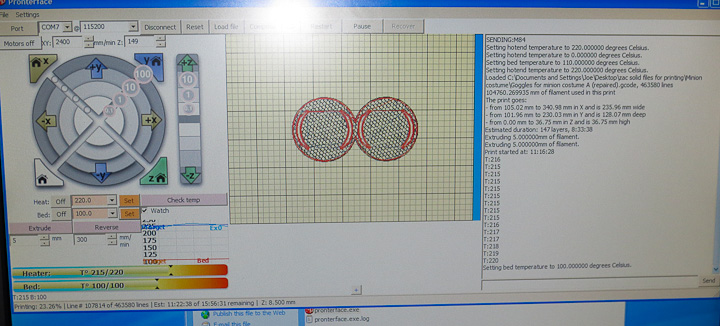
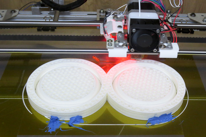
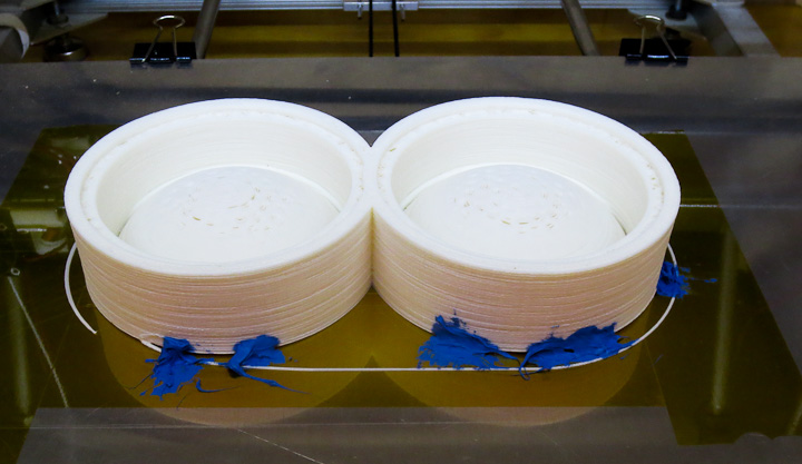
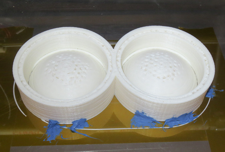
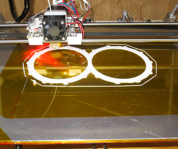
All of my previous posts on 3D printing used my machine.  I now have available to me one of the other types of 3D printing technologies, SLA.   This type of printer grows parts out of liquid resin, typically with a laser or projector system.  I’ve been using a Form1+ model SLA printer.  It’s a pretty fantastic machine with amazing resolution and detail.  There are also some great materials with different properties that I can not print on my Zac built FDM type 3D printer.   These include the Tough material I used to make the PCB grips for the old panavise clamp I wanted to put to good use for this project.  Formlabs tough resin is, well tough.   Meaning it’s not brittle like may SLA resins.  It also has a good feel to it and excellent mechanical properties for things like vise jaws.  The vise jaws are shown on the build platform after printing.  These are designed to slip over the metal “jaws” of the old Panavise I am using.  If you want to print out your own set of these jaws, circuit board vise jaws for panavise vice clamps.


FDM printed Vise quick attach mount

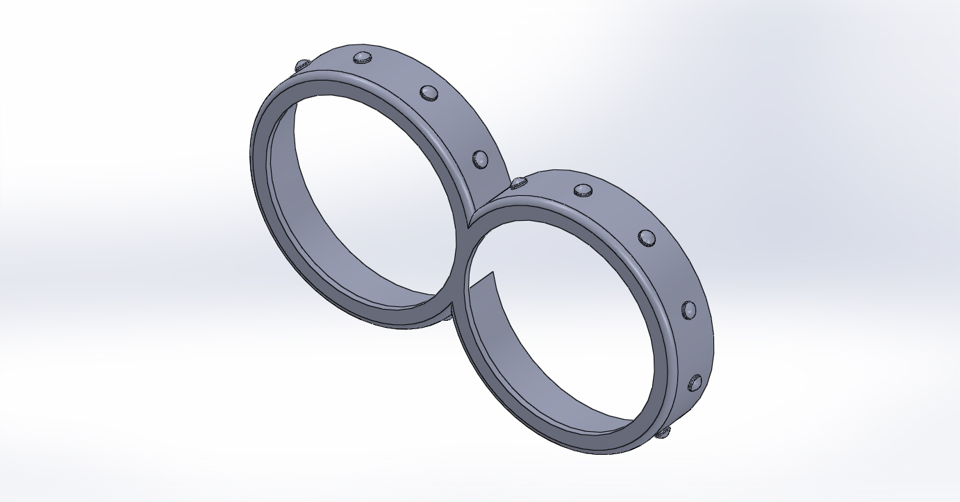
The other piece of the puzzle I needed to make this project work was a way to quickly attach and detach this vise from my electronics bench.  I do not plan to use this vise all the time.   It would be in my way a lot, meaning it needed a quick attach system.  I quickly drew one up and printed it out on my personal 3D printer.   I print in ABS and for this application this material is perfect.   Thequick attach vise mount for workbench.


081715  PCB holder 3d printed vise inserts-3551      081715  PCB holder 3d printed vise inserts-3550

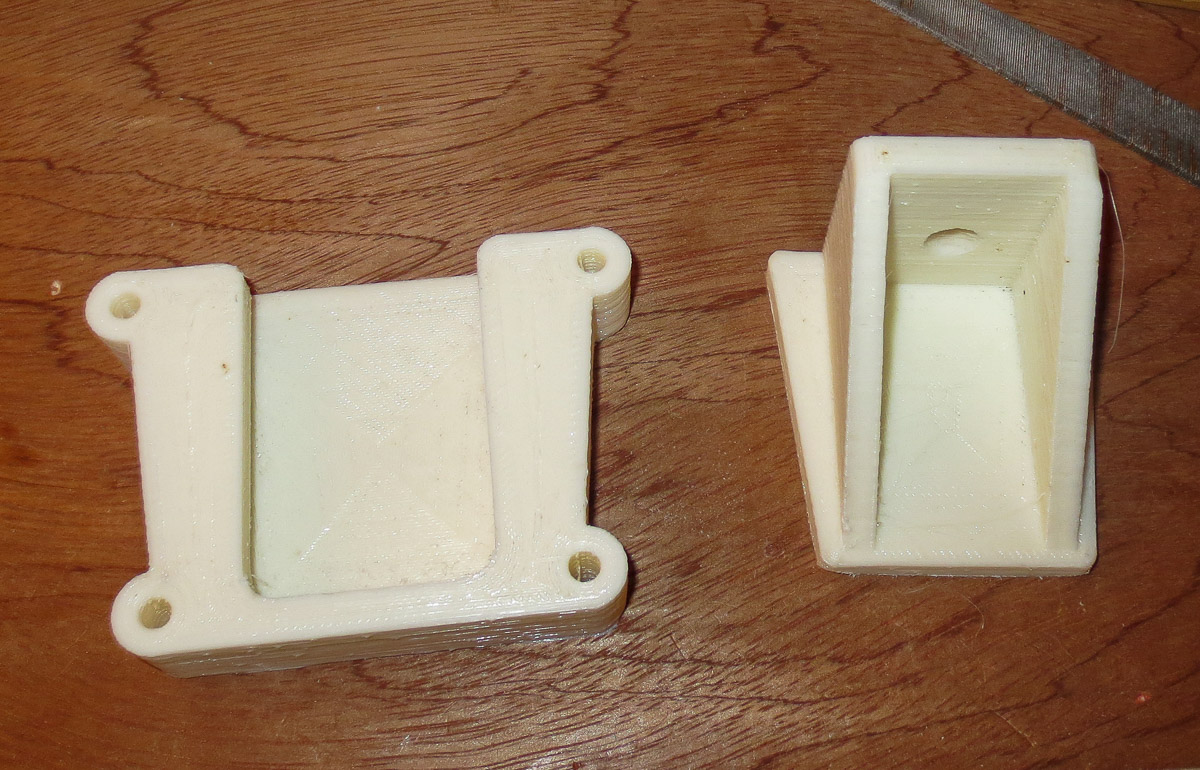
Both parts of the quick attach vise mount printed out in a few hours.   The mounting bolt on the panavise clamp is threaded 3/8-24.  I ended up using a bolt and a nut to tighten the clamp to the mount.

081715  PCB holder 3d printed vise inserts-3553            081715  PCB holder 3d printed vise inserts-3554

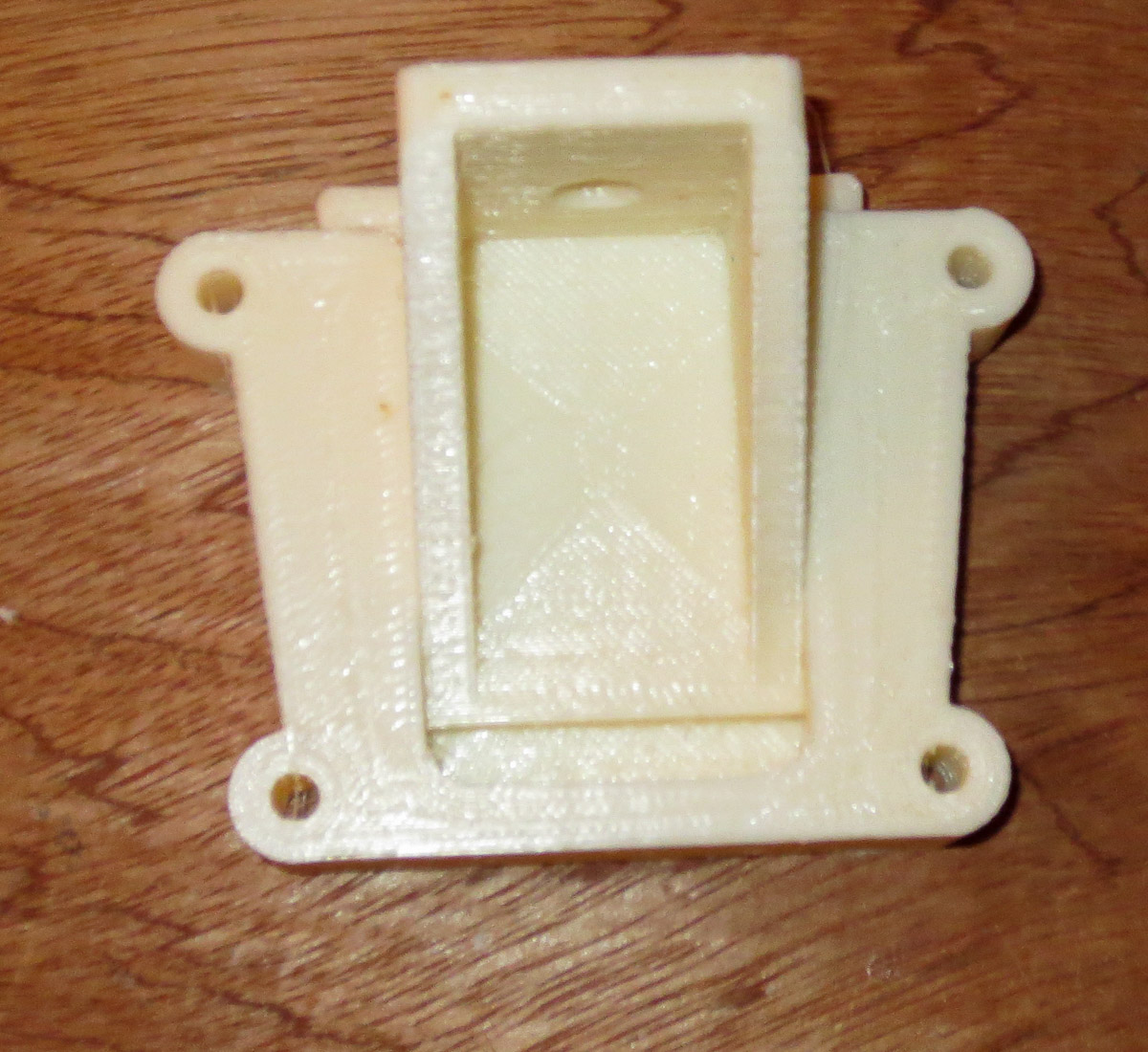
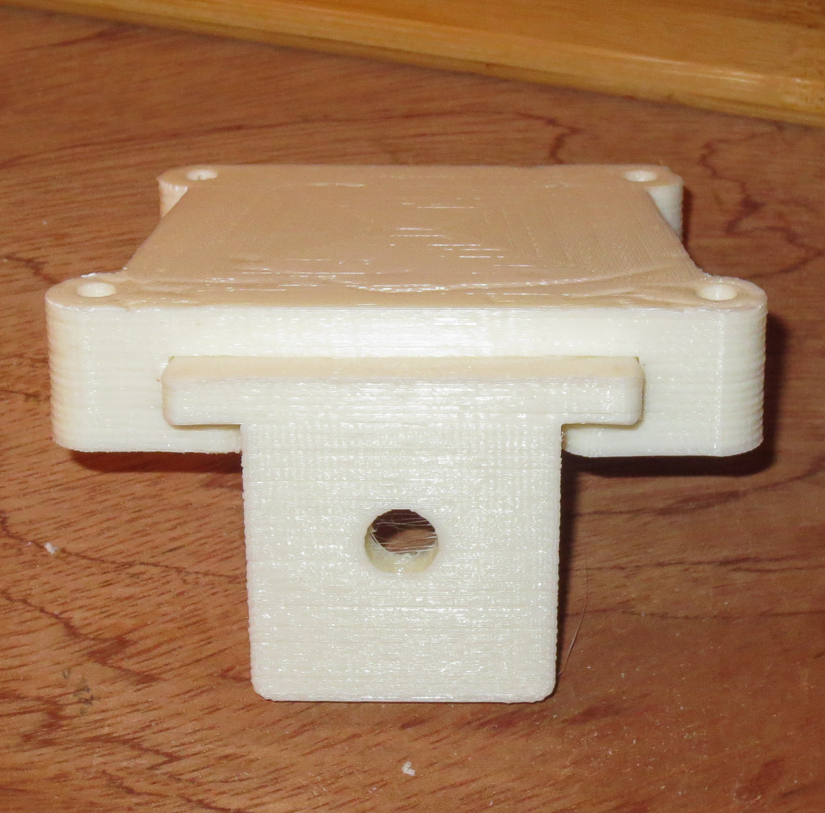
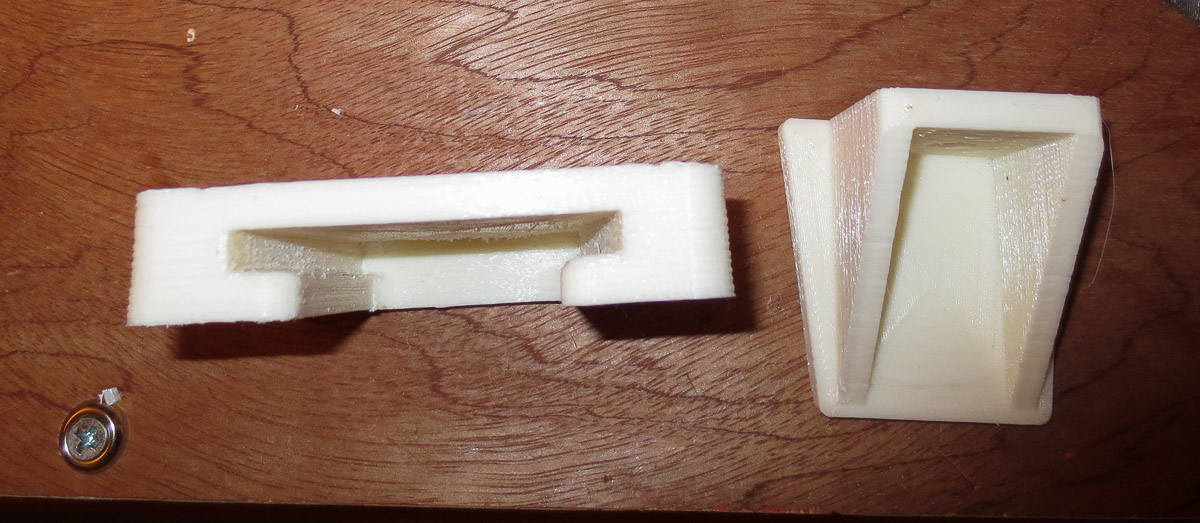
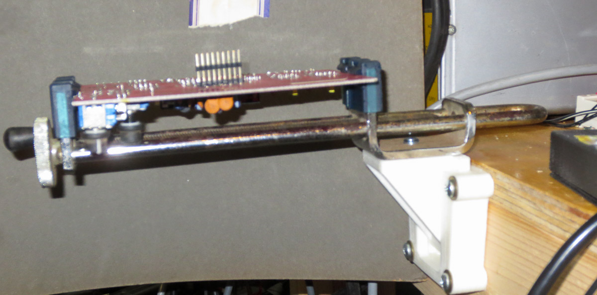
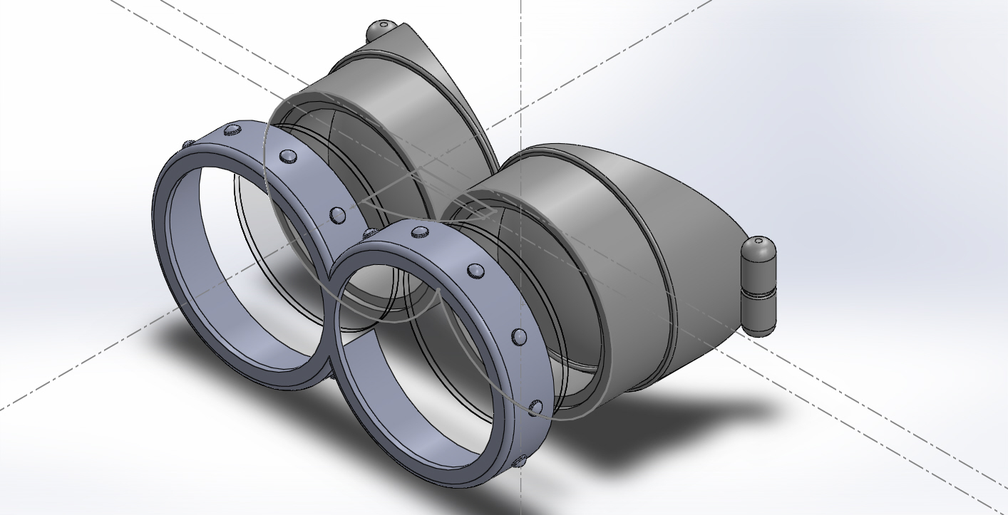
As you can see the two parts interlock.  there is a taper that locks the vise in place, but comes free with a quick tap upwards from underneath.

Panavise quick attach workbench PCB vise

Testing the location on the bench.  Can you see what’s wrong with my design.  I had a home ‘doh! moment when I saw what I did.

081715  PCB holder 3d printed vise inserts-3556      Printed Circuit Board holder

081715  PCB holder 3d printed vise inserts-3557

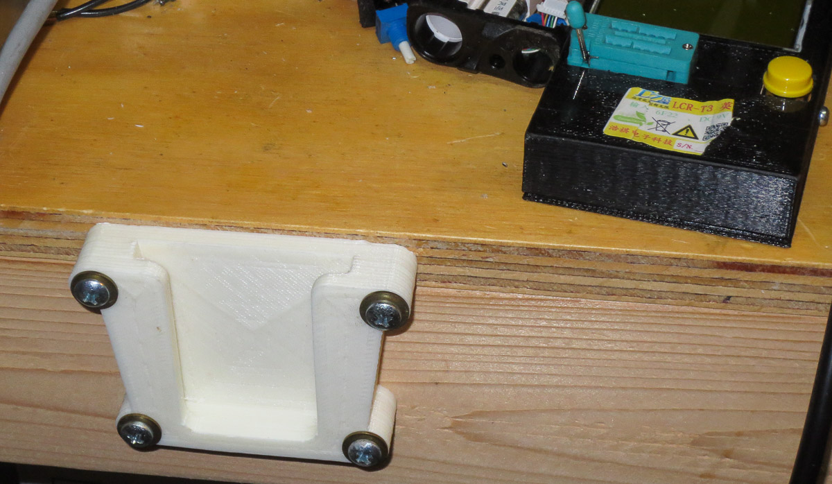
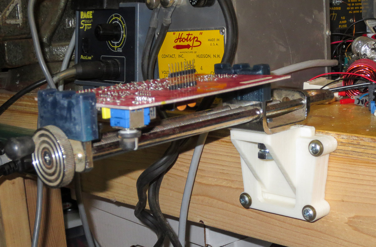
The thing I did wrong, is design the quick attach mount with the upper screws at the top.  The problem is that this design screws in edgewise to the plywood top of my workbench.  It is never a great idea to screw into the edge of plywood and expect it to hold.  This application is low force so I think I will be ok.  A better design would have the upper screw mounts 0.75″ lower, I will change my part files for others who want to use my design for themselves have a better design.

Printed Circuit Board holder

081715  PCB holder 3d printed vise inserts-3558

081715  PCB holder 3d printed vise inserts-3561

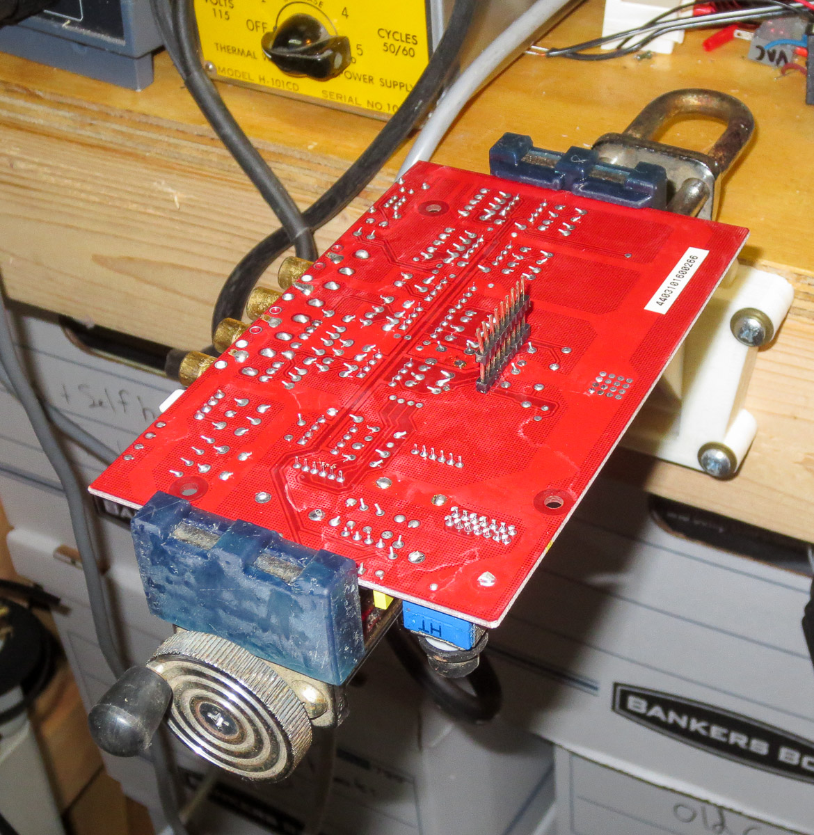
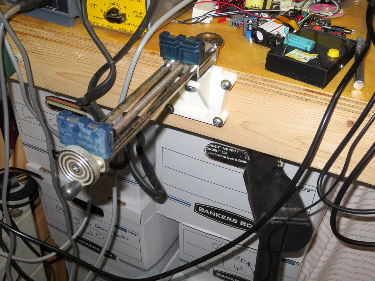
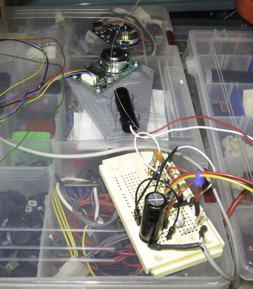
The above pics shows the vice holding an audio amp circuit board I needed to do some testing on.   As you can see the new PCB vise works great.  It can also hold smaller circuit boards vertically with the middle groove I added in my third and final iteration on the design.  I have used this great circuit board vise a handful of times already and I love it.

More on my other PCB holding and testing stations experiences in a future post when I have time.

The greatest electrical tool of all time, the LCR Tester!

Electrical component tester

This little guy is the greatest thing to happen to electrical projects since the invention of the hammer.  If you are like me, you have a million components on your bench or bins for electronic repairs, upgrades, and circuit design.  I stumbled across this tester on a forum and quickly ordered myself one from ebay.  You can find it by searching for LCR tester.  Why is it the best tool to add to your collection?  Well let me tell you….

measure resistors     Capacitor tester

First, it measures values of resistors and Capacitors (including ESR) with the push of a button.


Capacitor tester

It also does diodes…

Electrical component tester     Electrical repairs tester

But BEST OF ALL!  It tells you if  transistors, MOSfets, and the like are good.  But also tells you the values you need to work with these components in your projects.   This is why it’s the best thing since the hammer.  I have tons of components I’ve pulled from boards to use in projects, but finding data sheets etc is a pain.  This makes life easy, especially for breadboard proof of concept and educational circuit design experiments.

The LCR tester comes as a loose board, and is very cheap. I think mine was $15 shipped.  It runs on a 9V battery, and I printed a case on my 3D printer. I’ll find the model and share it here later.  This little device belongs on everyone’s electrical project bench (or toolbox).


PROJECT SNEAK PEAK:

LCR TEster pics-2780 LCR TEster pics-2782 LCR TEster pics-2783


Partially so I can find the driver board specs in the future, but I’ve been playing with Lasers for the last 6-9 months working on some different types of rapid prototyping machines.  More to follow but the sneak peak photos show some of my test parts as a tease.


Ducted fan designs, an early project sneak peek

3d printed ducted rotor aircraft engine

This post is an early sneak peek at a project I have been working on in my spare time.  I showed a friend who stopped by and he told someone else an I was pestered to share pics and a video.  I have been experimenting with ducted fan thrust generation with a planned application.  As for what  that application is…  Well it is not ready for the world yet and I will let you use your imagination.

thrust generating ducted rotor     3d printed ducted fan thrust generator

Mostly eye candy at this stage of the game, I have tested 3 different rotor designs without getting into complex blade geometries to date. I have primarily been focused on printing rotors that have little wall clearance and hand finishing them to minimize the gap between the duct and rotor blade.  Research papers I have read shows that this area is critical to ducted fan efficiency and design.

ducted fan design 3d printed-9400

I am currently using a set up with a friction fit on a taper to lock the two halves together so I can get at the motor.  This little bad boy screams when she spools up.  In the shop it sounds like a mini jet engine starting up.   I am working on test platform speed a controller for it using an Arduino nano and components..

rotor design for ducted fan

You can see that this needs lots of cleaning and smoothing before final thrust measurements.  I plan to put it through an acetone bath treatment and then do a bit of hand finishing to smooth out the inner walls to reduce any drag from the 3d printed irregularities.  Eventually I’ll make a rotor balancing jig to fine tune the balance on the rotor.  Future iterations will likely have continually reduced rotor mass to decrease inertia.  I am testing behind a 1/4″ polycarbonate shield in case of catastrophic failure.

ducted fan design 3d printed-9401Here’s one with my hand to provide you with a sense of scale.  I will try to get a video of it spinning at moderate speed.  Without a speed controller I’m reluctant to limit test the high speed operation at this stage of development.  I will put a video up here later this weekend if I can find time. 

How to Make a Minion Costume for Halloween– Part 2 ( 3D Printed Minion Goggles )

How to Make A Minion Costume Halloween-8500

This post is a continuation of my previous post and will primarily cover the design and printing of the Minion Goggles with eyeballs used  for my Minion Halloween Costume.  I spent the bulk of my costume time designing acurate 3D models in CAD software of the Minions eyes and goggles.  I wanted to make this the focal point of my costume and went to great lengths studying photos measuring toys, and watching the movies and shorts to get scale, proportion and details correct on this part of my Minion Costume for Halloween.  My goggles are designed to fit onto a 12″ diameter foam Minion head( ~11.5″x 5″x5″ dimensions.  My 3D printer is much larger then most of the hobby FDM style printers out there,  allowing me to build parts of  this size in one piece.  If you want to build one you can print it in smaller pieces and glue it up. I broke my model into 2 pieces so it would print easily and without wasted filament on support structures.

3D printed Minion Goggles

Above, you can see the software printing out one of the 3 pieces of my Minion goggle design. The current layer is highlighted in red on the screen.  I use Pronterface (seen above) and Slic3r to turn CAD models into plastic parts with my printer.  Both are amazing pieces of open source software built by the 3D printing community.  I printed it in 3 pieces to keep the weight down and use less filament.  The goggles when completed weighed in at ~1 lb. Quite heavy considering they are 6″  out from the center line of your head.  I designed the Minion Goggles to be printed as multiple pieces to simplify painting, allowing for true to character final product.  My Despicable Me Minion Goggle Design have 2 clear plexiglass lenses for that true “goggle” look.  This keeps dirt/food/stuff of the painted eyeball area and makes the eyeballs appear more glossy and lifelike.

3D printed Minion Goggles

3D printed Minion Goggles


3D printed Minion Goggles

The blue stuff in the above photos is Silicon RTV adhesive.  At about 4 hours into the almost 9 hour build there was some warping and pulling away of the parts from the Kapton tape covered heated bed build platform. I slathered on some RTV to prevent further warping and prevent the build from being ruined due to the part separating from the build tray.

3D printed Minion Goggles
I did not take a enough photos, this is the front Goggle lens retainer being built. I used support so the “rivets” around the outer perimeter would build cleanly.  I was careful to count, scale, and locate the rivets based on many photos and screen shots from the DVD.

3D printed Minion Goggles

This is the rear piece that will fit up against the foam minion head that I was constructing for my costume.  The head diameter on my costume is 12″ as this was the largest foam circular shape (more on this in Part 3 of Minion Costum Construction) I could find for a reasonable price.

Despicable Me Minion Costume Goggles Halloween - 2    Despicable Me Minion Costume Goggles Halloween Costume - Assembly    Despicable Me Minion Costume Goggles Halloween

I have uploaded the 3D cad models for my Minion Goggle design onto Thingiverse ( http://www.thingiverse.com/thing:232679 ) in both STL and an IGS assembly in case you want to make a Minion Halloween Costume of your own with some modifications.  Just remember that the goggles are designed to fit on a 12″ diameter head.  You can scale them if you are making a smaller costume for a kid.  If you use my files and make a costume, please send me a pic, I would love to see what you came up with and how it came out.

3D printed Minion Goggles      h

The raw printed goggles held up against the foam so you can see how they will fit on the Minion Head/helmet.

3D printed Minion Goggles   3D printed Minion Goggles

The painted goggles came out well.  In the above left you can see the acrylic disc that fits in the groove on the notepad. The outer frame is a snug enough interference fit that it retains them without any glue.   In my original design I was going to use foam for the helmet, however the foam ring was not up to the task of supporting the 1 lb printed goggles.  I cut a piece of 2 yellow pine into a ring for this purpose.   One more thing to note, should you follow in my footsteps on this DIY Minion Halloween Costume,  the weight of the goggles is too much without a counterbalance at the rear.  I attached with screws a steel plate(approximately 4 in x 6 in x 0.125 in) that I hammer formed to the 12″ diameter  counter the weight of the goggles.  This brings the helmet/head up to about 2.5 lbs.

minion goggles final

More on my Minion Costume Construction in the next and final post on Making a Minion Costume for Halloween – Part 3 where I will show you how I made the helmet, and talk about designing/making the fabric portions of my Minion Costume.