I have needed a printed circuit board vise of some sort for a while and have not found a lot of good affordable options that I liked. I had an old Panavise style hobby vise kicking around the shop for years and I recently decided it was the perfect solution for this project. I used two different types of 3D printers to make the parts for this project. My printer, an FDM machine I built myself was used to print up the ABS stronger quick attach mount to attach the vise to my electronics bench. I used a Formlabs Form1+ SLS 3D Printer to print the PCB holders/grips in a tough 3D printable material that was launched a few months back, appropriately called “Tough”.
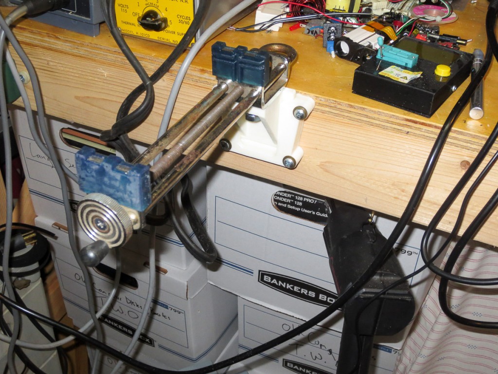
The backbone of this project is an old wide opening Panavise. These were a staple of the hobby world. I routinely see them for <$1 at flea markets and yard sales. I had this one kicking around in my metalworking shop for ages. I must have picked up somewhere for $0.25 as it still had the yard sale sticker on it. These originally came with a variety of low quality rubber “grips” and some sort of mount, often a poor quality plastic suction cup thing meant to quickly attach to your presumably smooth workbench. I gave away a handful of these to fellow hobbyists a couple years ago but this one survived the culling, and I’m glad it did.
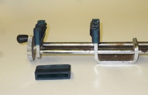
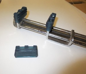
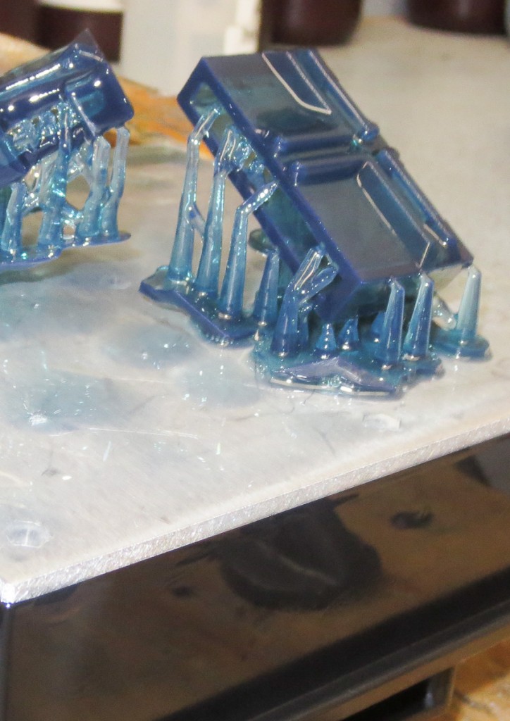
All of my previous posts on 3D printing used my machine. I now have available to me one of the other types of 3D printing technologies, SLA. This type of printer grows parts out of liquid resin, typically with a laser or projector system. I’ve been using a Form1+ model SLA printer. It’s a pretty fantastic machine with amazing resolution and detail. There are also some great materials with different properties that I can not print on my Zac built FDM type 3D printer. These include the Tough material I used to make the PCB grips for the old panavise clamp I wanted to put to good use for this project. Formlabs tough resin is, well tough. Meaning it’s not brittle like may SLA resins. It also has a good feel to it and excellent mechanical properties for things like vise jaws. The vise jaws are shown on the build platform after printing. These are designed to slip over the metal “jaws” of the old Panavise I am using. If you want to print out your own set of these jaws, circuit board vise jaws for panavise vice clamps.
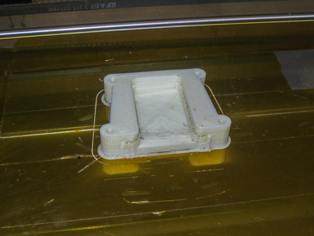
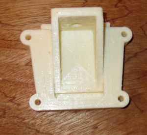
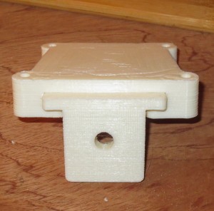
The other piece of the puzzle I needed to make this project work was a way to quickly attach and detach this vise from my electronics bench. I do not plan to use this vise all the time. It would be in my way a lot, meaning it needed a quick attach system. I quickly drew one up and printed it out on my personal 3D printer. I print in ABS and for this application this material is perfect. Thequick attach vise mount for workbench.
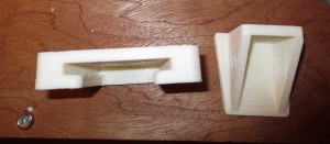
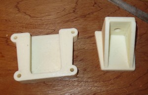
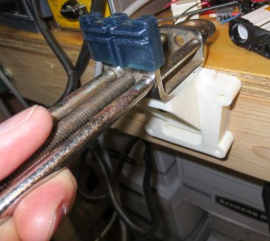
Both parts of the quick attach vise mount printed out in a few hours. The mounting bolt on the panavise clamp is threaded 3/8-24. I ended up using a bolt and a nut to tighten the clamp to the mount.
As you can see the two parts interlock. there is a taper that locks the vise in place, but comes free with a quick tap upwards from underneath.
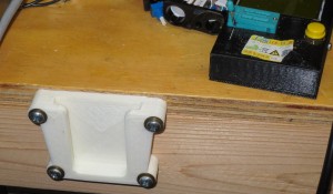
Testing the location on the bench. Can you see what’s wrong with my design. I had a home ‘doh! moment when I saw what I did.
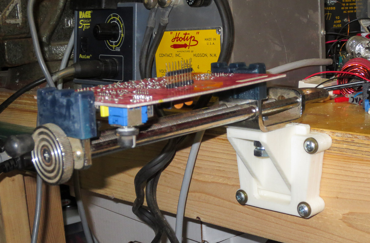
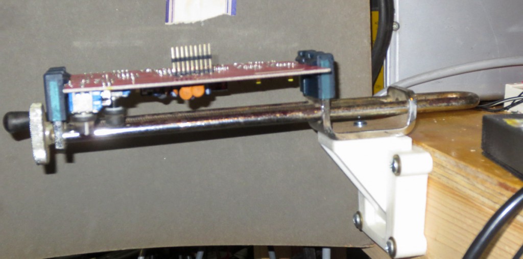
The thing I did wrong, is design the quick attach mount with the upper screws at the top. The problem is that this design screws in edgewise to the plywood top of my workbench. It is never a great idea to screw into the edge of plywood and expect it to hold. This application is low force so I think I will be ok. A better design would have the upper screw mounts 0.75″ lower, I will change my part files for others who want to use my design for themselves have a better design.
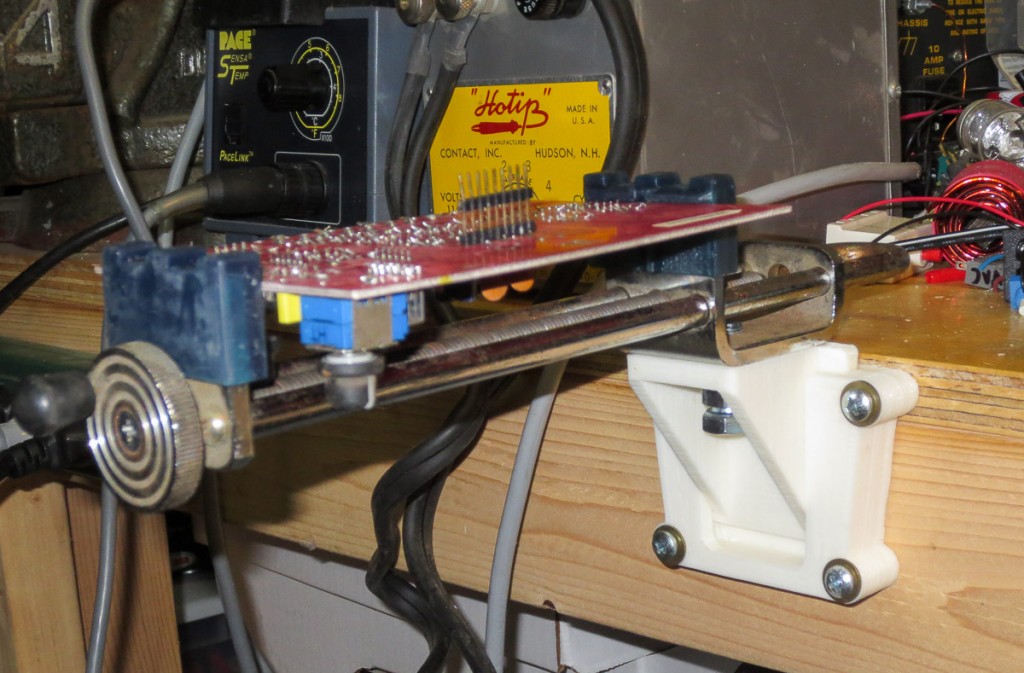
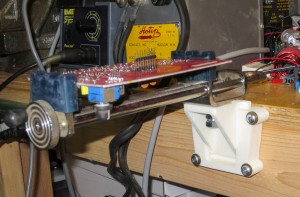
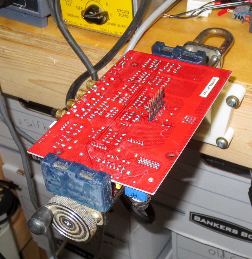
The above pics shows the vice holding an audio amp circuit board I needed to do some testing on. As you can see the new PCB vise works great. It can also hold smaller circuit boards vertically with the middle groove I added in my third and final iteration on the design. I have used this great circuit board vise a handful of times already and I love it.
More on my other PCB holding and testing stations experiences in a future post when I have time.
