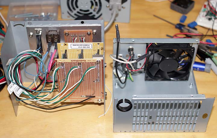
The reprap 3D printer project has been on hold while I work on other more critical items like upgrading the cnc machine and the holiday rush. I’ve got some pretty awesome friends who help me out with projects. This Makerbot Mk6 stepstruder was cut by one of my very good friends who happens to have access to a laser cutter at work. I supplied some acrylic and delrin sheet. When he had some time he stayed late after work to cut them out for me. Laser cut parts are a thing of beauty, especially in the frosted acrylic as there is a nice contrast between the crystal clear sides and frosted faces. Sadly I forgot to take pictures during assembly so here’s a link to the makerbot assembly instructions. I need to get a small digital camera for the shop area for project documentation. I promise to get better with this in the future.


The Makerbot Mk6 extruder is an elegant design. I really like the use of captive nuts and m3 screws to hold it all together. For final assembly I will use acrylic adhesive. I need to order and make a few parts for this unit. I plan on running it side by side on the bench with my cnc unit. Experimentation when they are both complete will determine which is a better print head / plastistruder for my 3d printer. I realize that I will need to do some significant lightening of the CNC plastistruder I designed to compete with the mk6 stepstruder in terms of mass/inertia.

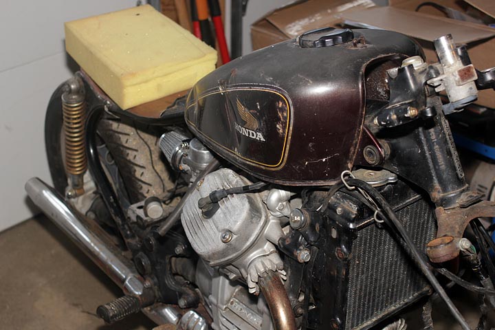
The picture above shows the “filament” going through the plastistruder. The print head for the Reprap style 3D printers is basically a micro sized extruder for molten plastic. A plastic wire, is fed through a sharply cogged pulley (missing in the pic) into a hot nozzle/head unit (the aluminum bit down bottom). Continually feeding the hard unmelted filament into the tightly fitting tube causes pressure to rise and the molten plastic to be extruded through the nozzle on the bottom (also not shown, use your imagination please). The computer will control the rate of extrusion and match it to the speed at which the printer is moving to produce a uniform printed layer of plastic. That’s the basic idea behind the Reprap based print heads. They have undergone a continual evolutionary improvement and will continue to do so into the future. I love the open sourced community nature of Reprap development. You get parallel and divergent development as different people work on their own units and try different things out.