I converted my lathemaster ZAY7045 milling machine (a RF45 clone) to 3 axis CNC about 3-4 years ago with whatever parts and materials I had on hand as a proof of concept experiment. The CNC conversion was one of the best things I have ever done. I instantly fell in love with CNC machining. At the time, I made the decision to run with the original very poor ACME threaded leadscrews with their 0.100″ pitch, AKA 10 turns per inch. My original conversion could hardly be called more than a down and dirty hack but it did work. Several problems with my original approach became apparent. First and foremost among my cnc machine woes was the ridiculous backlash on the factory parts, especially on the x axis leadscrew. I programmed and tuned anti-backlash algorithms in my control software that are quite amazing, but they only compensate for the backlash rather then remove it. With the extensive use the CNC mill gets the backlash had been growing worse steadily. When the backlash reached 0.047″ I decided it was time to replace the x axis ACME threaded leadscrew with a nice anti-backlash ballscrew setup.
A 20mm diameter ballscrew and associated ballnut were the largest that would fit under the saddle. As is often the way with tools, bigger is better when it comes to a ballscrew and it’s load handling ability. In this case it had to move a few hundred pounds of table, motor, vice, stock, cutting fluid, etc. I initially wanted to stuff a 25mm diameter ballscrew under the table, but after disassembly, careful measurement showed that it would not be physically possible to use 25mm diameter ballscrews. The new 20mm ballscrew will have a metric thread pitch of 5mm, roughly traveling twice the distance per revolution as it did with the original acme leadscrew. This is not a problem as the CNC software I use to drive my CNC mill can easily compensate for the change in the leadscrew thread pitch. The calculations to determine the new movement per step are basic and straightforward.
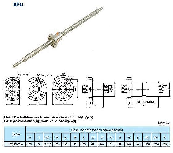
I don’t intend to wax poetic on the variety, quality, and types of ballscrews available. Plenty of companies offer excellent reviews of Ballscrew engineering calculations and selection criteria. I chose to use a 20mm ballscrew with a 5mm pitch (Part #: SFU2005-C7 ) of 975 mm in length, available from kellinginc cnc. See the dimensions and specs below.
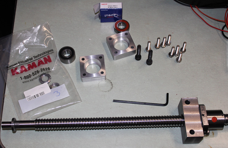
Dealing with Kelling Inc. is problematic at best. I have made four separate purchases from them, and twice I have had problems. One time they sent me the wrong part and then tried to make me use what they sent instead of what I ordered in spite of it not working for my application. Finally though, Kelling Inc. resolved that particular issue by sending me the part I ordered but it was a hassle to get them to do so. With the ballscrew, my issue was that unlike other vendors they do not including the 15mm x 1.0mm nut that threads onto the ballscrew to clamp it against a 5202 double angular contact bearing. Having used higher end ballscrews for industrial repairs and machine designs in the past experience shows that other vendors include this nut (a sub 1$ part) with their ballscrews. Kelling inc’s answer when I called to discuss this issue was that the nut is not included, nor available for sale individually, but I could buy their fixed end bearing mount BK15-C7 (Fixed End) for $82.95 and then get the 15mm x 1.0 mm pitch bearing retaining nut I needed. I was not about to spend $83 for a $0.87 part. With no solution offered by Kelling Inc. I set about finding the rare and elusive 15mm bearing retaining nut. Scouring the net and my supplier database from the day job I found an industrial supply company that would sell me a few of the 15-1.0mm bearing retaining nuts manufactured by whittet higgins, part number KM-02. I ordered my 15mmx1.0 nut from the local KAMAN Industrial Technologies office down in Manchester as they would sell to me with no minimum order fee.
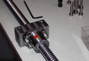
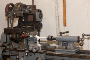
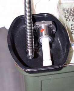
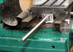
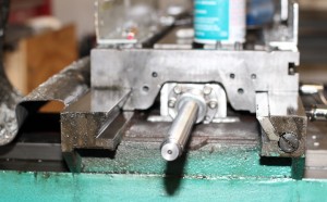
The ballnut came pre-installed on the SFU2005 ballscrew. It was installed flipped 180 degrees from what was needed to work with my design for my CNC milling machine. Removing a ballnut can be a lesson in frustration and hunting for hundreds of small ball bearings on the floor if you are not careful. The short lesson on how to correctly remove a ballnut is as follows. Machine a removal guide that fits over your machined ends and is the same outer diameter as the minor diameter of your ballscrews threading. For my SFU2005-C7 ballscrew this minor diameter is 18mm. I turned down a piece of sch 40 PVC pipe on my 100 year old lathe (yup it’s on the to be replaced tool list. As an aside, it will go to an industrial museum as a donation when I do eventually replace it with the shiny new 14×40 Lathe I have already picked out for myself). In the right hand pic above you can see that even though I used a ballnut removal tool, I still removed it over a tray. This is just in case something goes wrong and all of the small steel balls fall out. Better to be safe then sorry here, so use a tray.
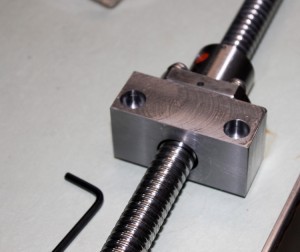
I designed the new ballnut mount to fit the original 8mm mounting bolt holes on the saddle. My ballnut mount design is such that there is no need to machine the ballnut. I did not want to risk contamination of the ballnuts internal raceway and bearing mechanism. my design lowers the ballnut below the raised nut mounting boss on the saddle assembly. There is very little clearance in this set up, but it works well and does fit. Here are technical drawings of my design: RF45 ZAY7045 mounting block for SFU2005-C7 ballscrew – sae units & in metric units RF45 ZAY7045 mounting block for SFU2005-C7 ballscrew – metric units
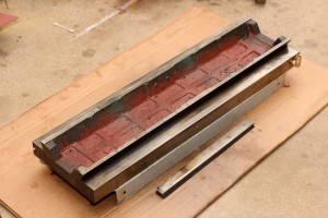
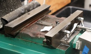
As you can see in the upper left photo, I had to clip the corners of the ball nut mount. This is not reflected in the above drawings, but you should machine the corners off the ballnut mount before disassembling your machine if you copy my design. I did it by hand with a carbide burr and hand files. Also note that I have not yet installed a zerk fitting into the ballnut. I hope I can find a tight M6-1.0 90 degree Zerk fitting that will fit and clear the table. For now I plan to use grease on the ball nut. In the future I will add a self oiling system to the CNC machine and will convert the ballnut over to oil lubrication at that time. Oil lubrication is superior in that it tends to wash away contaminates from the ballnut rather then collect them as grease does.
That is all for part 1 of the ballscrew upgrade on my CNC milling machine. This post continues in part 2.

Hi guys, I have found the best quality Ground Ball screws from ROTOLINEAR SYSTEMS in Bangalore.It aims to provide right Products & solutions to Major CNC Machine tools builders, SPM Builders & Machinery builders.
If u want more details about this….
just click here…@http://www.rotolinearindia.com
Looks like Rotolinearindia has a large motion control product range so I’m letting your comment stand. Do you sell single items to individuals?
Hi there,
Wow…Nice work. I wanna do the same… rebuild milling machine into CNC.
I have a question. How you deal with side clamps on X and Y axis. They need to be off all the time. If there is a play in dovetails any ballscrews are useless.
Or maybe you have to tight them but not too much and use smaller mills for job….I don’t know…
regards,
California, Los angeles
I’m not sure what you are asking about the side clamps? Do you mean the screws that press on the gibbs that are used to lock the table in place? I have them backed out entirely on the machine so they don’t cause the table to bind. Most machines have adjustable gibbs (looks like this: http://www.practicalmachinist.com/vb/attachments/f9/1796d1203373617-milling-machine-gibb-gib1a.jpg ) in the dovetails. You can control the play in the dovetails by turning the screws that hold them in place so there is no play on your slide table with some careful adjustment. This is how you compensate for any wear over time as well.
I purchased a new rf-45 with a broken x-nut. After pulling it apart and receiving a replacement part I noted that the tap of the attachment points is not perpendicular to the bed travel and thus adds a lot of stress to the screw. I have thought of replacing the screw with an alternate screw and nut assy (such as a ball-nut or the Teflon coated kerk line) but am not sure how to go about re-tapping screw hole locations. Just wondering if you had any ideas on how to proceed with this line of thought. I assume that you were able to put your nut into the table without this concern. I’d love your ideas. -Chet-
There is a lot of material machined flat on my “carriage” ( I will use this term for the large casting between the table and the base with dovetails on top and bottom) you could easily machine some new screw locations into the cast iron a bit offset from the original ones. Likely this would require you taking the carriage off and doing the drill and tap on another machine. If you were really careful and made yourself some sort of drilling guide out of a chunk of steel that clamps to the original bolt hole locations you could likely do it without removing the carriage but it’s better to take it off and do it right IMO. You could use a large drill press or take it to a machine shop to have it done. There is not a good way to fix poorly drilled and tapped holes in the original locations. There’s plenty of leeway and space to move the x axis nut and shifting it 3/4″ or so is not going to realistically lose you travel.
Zac,
Did you have to machine a lot on your carriage?
I am having a hard time getting my 20mm ball screws to clear the table with conventional mounts so I am going to try what you did.
Thanks JC
If you look at part 2 you can see a pic where I had to grind/file away some of the table to make the nut assembly fit underneath the table. It was not much but I had to make room for the “corners” of my steel mount for the ball nut.
I am converting an rf 45 clone right now. I appreciate your pictures and descriptions. You posted a drawing of the ballscrew saddle mount. Will that mount work for both the X and the Y if the corners are cut for cleance?
Thanks
Jon, It will not work for the Y axis. I haven’t converted my Y axis yet. I’ve talked with a couple guys that have and there are two approaches. One is to use the boss in the saddle like the OEM nut, the other is to use a plate on the back side of the saddle, machining a couple tapped holes into it to mount the ballnut. When I get around to this upgrade I will be sure to make a few good posts on how I did it and share my drawings for the Y axis.
Hi Zac I have just brought myself an AMA 45 I think its a clone of the 45 range. My question is would a threaded nose ball nut fit under the table? The OD of the ball nut is 40mm the threaded nose 38mm x 1.5. The ball nut screw is 25 OD x 5 pitch.
Kind regards Trevor j.
I don’t think there’s any way to make a 25mm ball screw fit on these machines. There’s only just barely clearance for the 20mm ballscrew/nut. And that was with me machining down some height off the ballnut.
Hi
What did you do for the z axis ?
Do you have the blueprints of the parts you had to make ?
Hey Zac
I have the same ZAY7045 Mill and would like to replace the leadscrews with ballscrews and you show the size of the part for the X axis (20mm x 975mm) Given you’ve had you’re machine apart did you take the measurements for the X axis ballscrew upgrade?
Thanks in advance,
I’m not certain what you are asking here? Can you please clarify why measurements you are looking for and I’ll look through my notes and see if I have them for you? I’ve used this machine so much I’m about to tear it down to rebuild the head as I have a bearing going. I may be able to help you when I do this as I plan to finally upgrade the Y axis leadscrew with the ball screw I purchased years ago and mill out the bass to allow for a bit more travel.