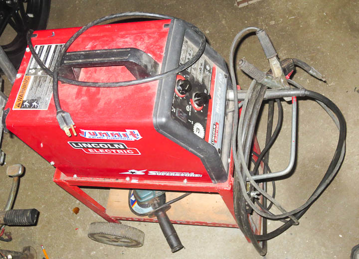
 While working on another project, a diode shorted out in my Lincoln Electric Welder, a Weld-Pak 100. I needed to replace this diode but finding information online was challenging. To help others, and myself in the future, I am sharing data and specs for the replacement parts I ordered to fix my Lincoln Welder. I knew the issue was a diode and not a transformer short because it still made an arc (very poorly), but became a buzz box with the right sound without throwing the internal breaker. A short in the transformer would likely trip the breaker quickly and not continue to generate an arc. Opening up the weld-pak 100 and testing the diodes with my digital multimeter with it’s diode setting quickly identified the problem diode. To do this you have to first remove the diodes from the aluminum plate that acts as their heat sink (or at least the output wires from the plates).
****This project, like many projects by Zac is not a task for the unskilled or those lacking knowledge. Electricity is dangerous! It can and will kill you!***
If you don’t know exactly what you are doing to be safe, do NOT attempt any kind of repair like this. Always unplug, and check (verify with a meter safely) that any and all capacitors are discharged fully before testing or working on any electronic device. I’m sharing this info, primarily to have the data easily accessible should I need to replace or repair my welder again in the future.
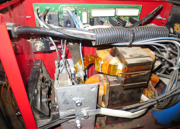
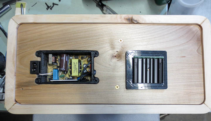
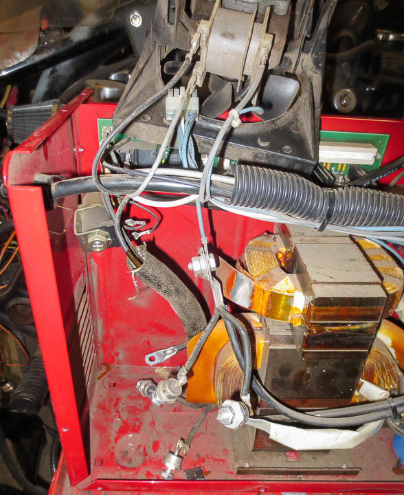
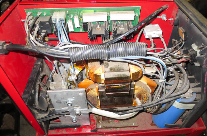
The Lincoln Weld-Pak 100 diode replacement is a huge PITA. There is not one smidge of extra wire inside to allow things to move freely making it challenging to work on. In addition, the transformers are made from wide aluminum strips, and it’s pretty much impossible to move this aluminum strip in the wide direction. The trick I found to getting the diodes out (they are attached to the rectangular aluminum plates on the left bottom of the above photo) is to undo all of the bolts before trying to get at them.
 Removing what passes for the heat sink (aluminum plate pictured above) from the welder is problematic as well. Working on this welder is not easy because there’s not a lot of wiggle room on any of the wires. From a design standpoint this makes sense, least amount of wire will result in the lowest losses. To get the heat sink plates out use a thin screw driver to pry the inside plastic clamp and pull the plate towards the front and then up. I broke off one of the little tabs that locks the plate in place due to prying a bit too much. Thankfully there are two on each plate.
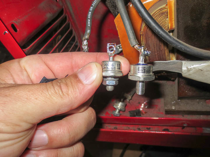 Above is a side by side photo showing the original diode on the left and the replacements I ordered on the right. The original rectifier diodes used in the bridge rectifier assembly to generate the DC current used for welding are International Rectofier parts: IR M9661 40RU (reverse configuration) and IR M9661 40U. There are 4 diodes in total, and 2 of each part number making up the bridge rectifier assembly. One of mine was blown, being shorted out such that it allowed electricity to flow in both directions. These diodes are rated at 70A and 300V based on what I could find on the net, in welder forums and user groups. The original replacement parts are available from Lincoln and welding supply companies for about $24-30 each. While that is an option, most of the welder forums recommended replacing the diodes with higher voltage ratings as often they blow due to repeated voltage spikes during the welding process. I decided to replace all 4 o the diodes in my Lincoln Weld-Pak 100 Welder. I started my search for replacement parts at Digikey.com (my favorite supplier of electronic parts) but they do not stock higher power rectifier diodes. I ended up finding what I needed at Newark.co. There were lots of options to choose from, my choice might not be the best one. If you follow in my footsteps understand this fact. I as not 100% certain the diode replacement would entirely fix my welder, as such I went with the cheap option. I ordered two Solid State 85HFR120 and two of Solid State 85HF120 diodes from Newark.com with a total cost plus shipping of considerably less then one replacement OEM diode. These diodes had the same form factor as the originals and are rated at 85 amps forward current and more importantly a much higher repetitive reverse voltage max of 1200V.
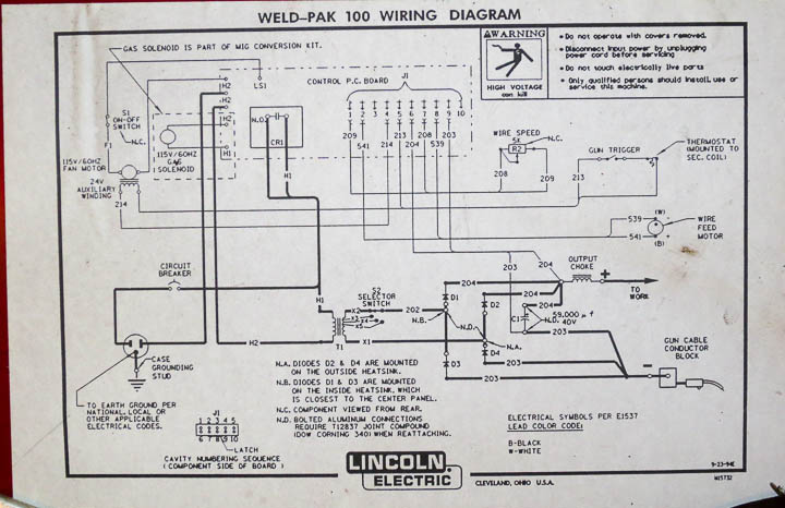
Above is the wiring diagram for the Lincoln Weld-Pak 100 Welder. Thankfully it was inside the welder. When I looked online I couldn’t find a wiring diagram for my Lincoln Electric Welder and thus I’m sharing it here. Sometimes it is nice to find things like the circuit diagram for your Weld-Pak welder before you open it up.

In order to get the second aluminum plate heat sink out from the welder I had to completely remove the fan assembly. The plates are supported as well as electrically isolated by the fan assembly so be sure to go careful and not break anything. When you put it back you need to be very careful that everything is floating in air and no uninsulated parts are touching any other metal parts. This welder uses air gap to electrically isolate some of the components.
*** Special note *** DO NOT CUT THE WIRES TO THE DIODES! There is no extra wire, you MUST DE-SOLDER the wires, and then put them through the new diodes for soldering! Yes this is not easy, but trust me, if you cut them you will not get it back together without having to replace more things and take the entire welder apart.
Replacing the Diodes on the Weld-Pak 100 is pretty straight forward in theory. Desolder the wires from the old parts, solder on to the new ones. You may have to squish the wires while hot with needle nose pliers to get them through the new diodes, or wiggle them in while the solder is melted (using tools not fingers, melted solder is hot). With all of the diodes replaced you are ready to carefully reassemble the diodes and heat sink plates. I’m not sure one way is easier then the other. I put the aluminum plates mostly in place but not fully. This way I could wiggle things into place and then tightened down the nuts. BE SURE TO USE HEAT SINK PASTE ON THE DIODES when mounting to the Aluminum plate. I did not have torque specs on the diode nuts, I just made them tightly snug. Enough so I was sure they wouldn’t come loose, but not tight enough to break anything.
 Once you have it all back together, be sure to check that you have nothing touching that is not supposed to be touching. I used a little bit of Kapton film to insulate the transformer “wire” strip on the off chance that something came in contact with it in the future. I loosely layed the cover back on and did some test welding. The welder worked marvelously. I suspect perhaps my diode was iffy for a while as I was once again getting that nice sizzle sound from mig welding. I realized on hearing it I had not heard that sound quite right for some time. The bead of weld my weldpak 100 layed down was perfect. I’ve since welded quite a bit with the repaired welder and everything seems to be great having replaced the rectifier diodes on my Lincoln Weld-Pak 100 Welder.
If you found this post useful, let me know, leave a comment. It’s nice to hear someone found my post useful.