Category Archives: RF45/ZAY7045 CNC Milling Machine

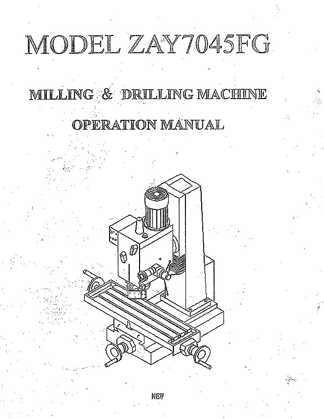
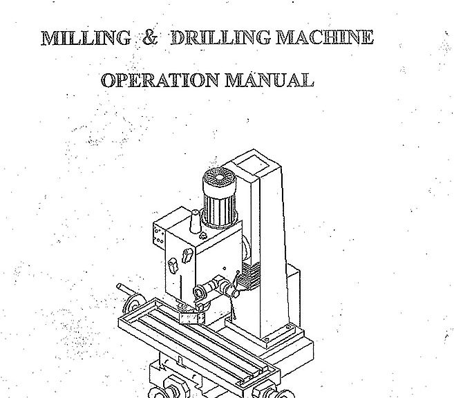
ZAY7045FG Milling Drilling Machine operating Manual PDF download

I couldn’t find this online, found close but not exact. After lots of looking I found the original paper manual which I scanned to make this file. Truth, I didn’t clean it up, but it’s all there. I’m hosting this primarily for my own personal future reference but I also hope it helps someone else out with one of these great machines. I have ~3000hrs on mine most since it’s CNC conversion many years ago (link to posts) and a bearing is finally going. It’s nice of them to list the bearings part numbers out in the manual. Time for a rebuild for my overused and highly abused mill.

Download link to the user manual for my RF7045 mill drill clone in pdf format below.

http://www.projectsbyzac.com/wp-content/uploads/2021/02/MODEL-ZAY7045FG-Milling-and-Drilling-Machine-Operation-Manual.pdf

A quick easy way to make an XL series timing belt mount

XL timing belt mount

Timing belts are useful for all sorts of synchronous motion.  They can be used to connect a rotary encoder to a lathe spindle or to provide linear positioning on a 3D printer.  They have little stretch or flex and can accurately transmit rotational motion.   One of the challenges with using timing belts is mounting them in your projects.  This is especially true when you want to use timing belts to convert rotational motion of a computer controlled stepper motor into positionally accurate linear motion on a project like my 3D printer build.  Here’s a fast and easy way to make yourself a timing belt clamp and mount for your project.  The clamp shown in this post will function as the y axis mount on my DIY 3D printer (photo installed at the end).

how to make a timing belt clamp using hot glue-1645

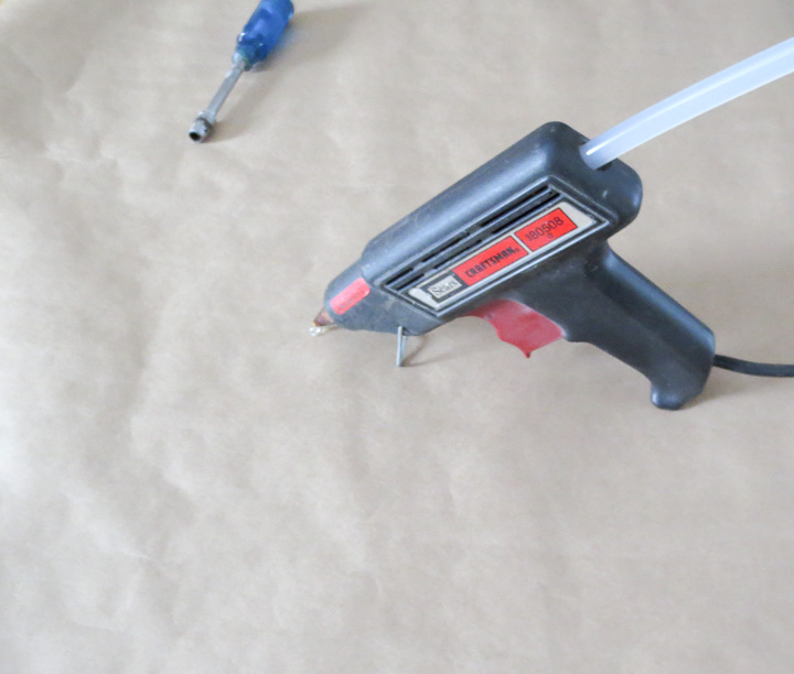
Any craftsman, maker, car guy, or project loving person knows about and owns a hot melt glue gun. They are good for many things,  in this project the hot melt gun is going to provide the plastic uses to pattern our timing belt interlock features on a substrate.

how to make a timing belt clamp using hot glue-1648    L series timing belt clamp

Wear gloves when playing with hot things!

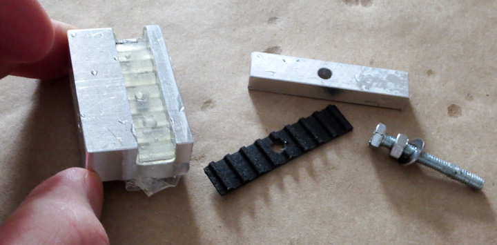
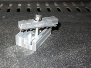
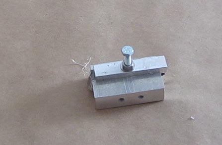
First you need to make a mounting block for use as a substrate from your material of choice.  Aluminum in this case.  I machined the part to fit onto my 3D printer’s y-axis structural cross member.  I cut a small scrap of XL series timing belt to fit the groove. This is why it is always good to hold onto things like a scrap bit of timing belt.  It may be hard to see in the picture above but I drilled a series of 6 shallow holes into the timing belt slot to allow the molten hot glue to seep in and form mechanical interlocks.  It’s best not to rely on the adhesive strength of the hot glue, mechanical interlocking features for the polymer to mold into provide good shear resistance.

Pre-heat the substrate.  You could use a project toaster oven,  heat gun, 500w lamp, etc.  I used the woodstove.  If you try this with a cold substrate the hot glue will cool too quickly to mold to the features of the timing belt. You want the substrate warm so it does not pull heat out of the molten polymer before we can mold it to the timing belt.

XL series timing belt mount using hot glue - 7

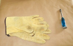
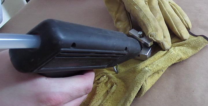
Quickly take your preheated substrate from your heat source, put it on a nonflamable surface (leather glove in this case) and fill both sides with hot glue quickly.  Use a bit more then you think you need, it will seep out the ends if there is too much in the slot.

XL series timing belt mount using hot glue4

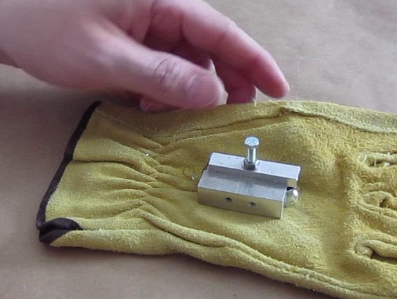
Then clamp down the timing belt into the molten plastic with the screw. I used a long screw to provide alignment and a nut to make clamping  easier and faster.  It is also acceptable to just squish it down with your fingers.   Put the hot assembly into cold water to quickly cool the hot melted plastic before it can seep out of the cavity.

XL series timing belt mount using hot glue

Let it cool completely before disassemble.  I’ve never had any issue with the hot glue sticking to the timing belt enough to be a problem.  Usually it is possible to remove the Timing Belt used to mold the plastic with fingers. If it is a bit stubborn in coming free use a small pair of pliers to get a grip on the bit of timing belt and slowly pull it up and away.

XL timing belt mount

When disassembled, trim up any of the plastic that seeped out with a sharp exacto knife or chisel.   As you can see you get a perfectly molded Timing Belt clamp that can be used for your project.

XL series timing belt mount

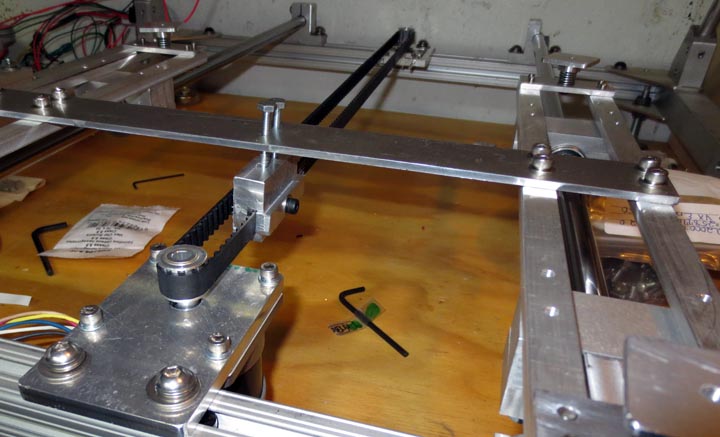
Here’s the finish timing belt in place on the 3D printer project.  The stepper motors have 10 tooth pulleys on them to drive the XL series timing belts allowing the y axis to move with positional accuracy.  More on the 3d printer progress as I have time to write.  It is nearly operational!


How to CNC machine a part from start to finish

Several readers have asked me for a post explaining the entire part creation process starting with a part concept, going through fabrication and ending with the part in use.   I use a ZAY7045 (RF45 clone)   Milling machine that I converted to CNC  to make parts for my projects.  In this post I will be sharing the details on the CAD design of parts, CNC coding, and fabrication process.   I will be using a two different pieces ( a headlight mounting bracket  and a speedometer mounting bracket) I made recently for my Honda CX500 Cafe Racer build to illustrate and outline the basic process of CNC fabrication of custom components.   I will keep the details simple such that everyone can understand how the CNC fabrication process works.
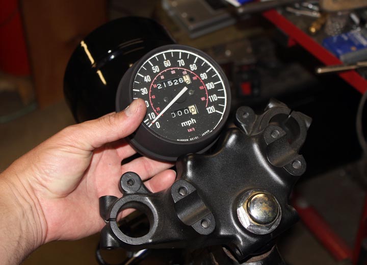
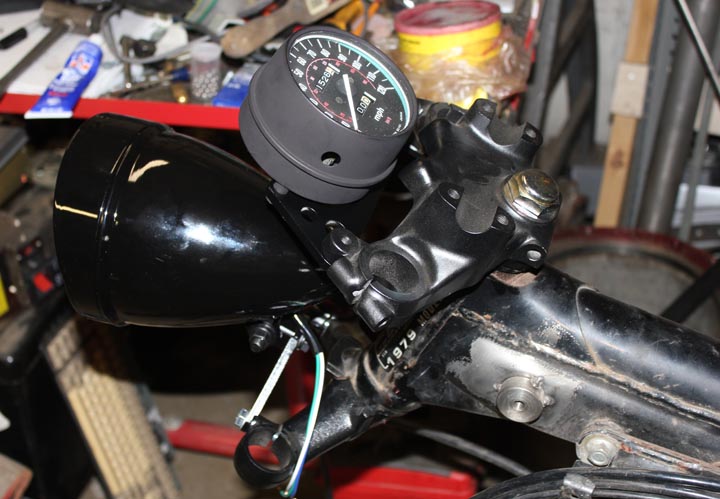
Speedometer mounting on a CX500 Cafe Racer

All parts start with a need,  in the photo above,  I need a bracket to locate and mount a single gauge to the upper triple clamp on my Cafe Racer Motorcycle Project.   I start by holding the speedometer gauge in place and taking some measurements.  It’s critical to carefully measure details like mounting bolt hole spacing.   As a rule of thumb I measure the smaller and larger dimension and take the midpoint between those numbers.    Here’s a Zac Shop Tip:  if you measure and calculate 138.43 mm,  it is very likely the actual value is the next nearest whole or half number,  ie. 138.5mm. After writing down the measured values on a small notepad, I next go to the computer to draw up the part.
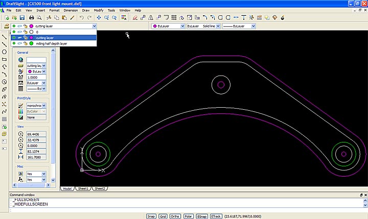
Cad drawing of cnc machined part with different layers for different operations

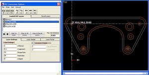
After careful measurement, it is time to draw up your part in a CAD software package.  I’m quite fond of Dassault Systems, Draftsight software for generating simple DXF and DWG drawing files.  I am familiar and proficient with Solidworks, a 3d design software package which makes using the free Draftsight .dwg/.dxf CAD software an easy experience.  The above screen shot shows my version 2.0 headlight mounting bracket as drawn in draftsight.  You can see the part layer in white, the cutting layer in magenta, and the milling layer in green.  I manually set cutter offset in my drawings (a topic for another more technical post).  Each layer will have a different code generation step in the next part of the process.  Separating them out here makes life easier later on when generating the G-code for the CNC Milling Machine.
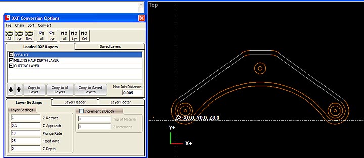
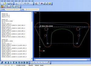
The CNC code generation software I use is not great, but I can not afford very expensive enterprise level software for this stage and thus I make do with what I have available.  I use this software to put the basic building blocks of the code in place.  I then rearrange, and edit the Gcode (CNC Machining programming language) into a form that is more usable and efficient.  The above photo shows a screen shot of the step in the process where I can set individual layer settings for the cutter.  You may recall I explained the need to generate separate layers earlier in the post and this is the purpose.  If you do not separate operations into layers you end up having to do a lot of tedious manual editing of your CNC Gcode program.
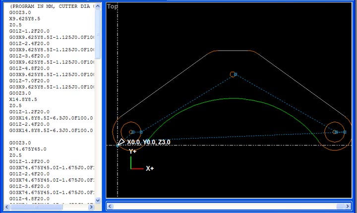
CNC Gcode generation

After chaining the layers together, so that the machine can generate code that does an entire loop in one go vs each individual drawing item  one at a time,  the software generates a basic G-code program.  I then carefully reorganize, and edit the code to make the program safe, do what I want, and in most cases more efficient.  The software tends to break things down such that the machine spends a lot of time traveling between points of entry into the material.  I reorganize the code snippets to minimize this which in turns shortens the machining time considerably.
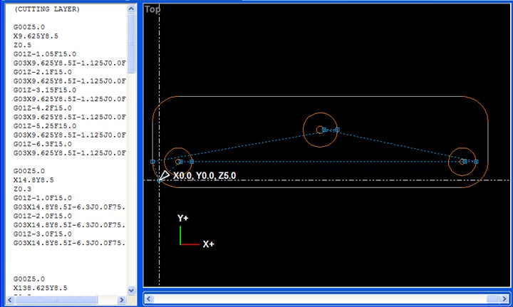
The above photo, is the Gcode generation for the v1.0 headlight mounting bracket.  I made this first part as a fast test of the mounting location and strength of the 1/4″ thick 6061 aluminum plate I would be making this part from.  I will use this part in the next couple pictures vs the V2.0 headlight mounting bracket we’ve seen in the post so far.  I did not plan to put this post together ahead of time and missed some pics in the process with the v2.0 mount.   Rather then wait till I build the next part, I wanted to get this up to help my readers understand the process as soon as possible.
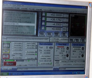
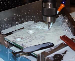
CNC machine software controlling the milling of a part   

Above you see a screen shot of the CNC machine control software running the machining process.  After lots of careful checking and setting a zero point on a larger piece of metal “stock” clamped into the machine I start the program and the machine does the rest.   This is really fantastic when you are making 4 of one part as after the first time the code has run through and is validated I will start the program and leave to do other tasks in the shop.  My CNC machine is not 100% self sufficient yet, so I periodically monitor it when it runs.  The number one problem with my current set up is coolant spraying everywhere making a real mess.  I plan to place the machine in a full enclosure at some future time.
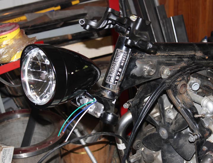
CX500 cafe racer headlight mount Ver 1.0

The above photo shows the cafe racer headlight mount version 1.0 in place on the bike.   While this was a functional part, I learned I needed three changes for version 2.0.  The first change is that version 2.0  needed to be less ugly.  Aesthetics are important on some projects, and my Cafe Racer is to  be a thing of beauty.   Secondly I learned that I wanted to raise the headlight another inch or so in version 2.0.  Third I needed a slot to keep the headlamp from rotating, especially important to prevent it rotating with riding vibrations over time.
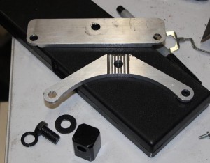
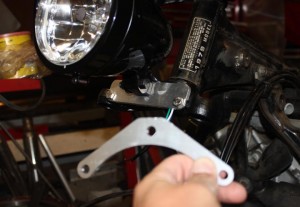
    CX500 Cafe Racer custom CNC fabrication

Above you can see the version 1.0 and version 2.0 parts together.  Clearly version 2.0 is superior in every way.
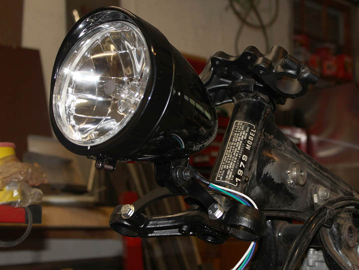
Custom CNC cafe racer parts built to orderAbove is the finished and painted bracket with the headlight mounted on the bike.   I am quite happy with the way it came out in the end.
     CX 500 cafe racer CNC fabrication

Similar to the headlight mounting bracket, I generated the code for the gauge mounting bracket for the speedometer.  This program required considerably more reorganization of the code to make run efficiently.  I use a simulation to determine the program run time.  The “as generated”  Gcode had a run time of almost 45 minutes.  I managed to get that down to 28 minutes by manually editing and reorganizing the G-code in the program.
CX500 Cafe Racer parts made to order   

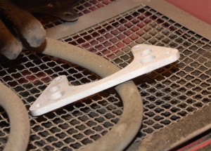
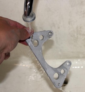
Now for a bit on post CNC machine processing of parts.   I start by deburring all of the edges with either a deburring tool, a fine file, or sandpaper.   The machining process often leaves razor sharp burrs on the edges where it cuts the metal. The  parts used as examples in this post were primarily deburred with sandpaper.  I then wash them with warm soapy water to remove any cutting oils and coolant left on the part.  A quick trip to the sandblasting cabinet and they are left with a fine surface finish ready for paint.  Another trip to the shop sink to wash off any residue sand from the blast cabinet and they are ready for painting.

I often paint small parts like these brackets hanging from bits of bent copper wire through a bolt hole.    Several light coats of a quality paint results in a hard durable finish.  A hairdrier (buy one especially for this purpose, do not “borrow” your significant others for painting car parts) can be used to help flash dry the paint between coats, or in the winter time cure the paint quickly in colder temperatures.
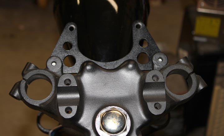
Cafe racer guage mount speedometer

Here’s the finished CNC machined bracket on the bike.
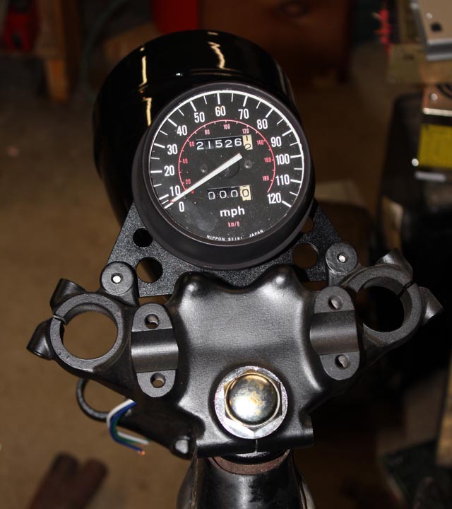
Cafe Racer Speedometer  CX500

    I am very happy with the way these parts came out and the overall look on the bike as this project progresses.  If you want more information on these parts (drawings, etc)  or would like me to make one of these parts for your CX500 motorcycle project,  leave a comment on this post or email me at zac at projectsbyzac.com.  I hope this helps my readers understand the process of how to make parts with a CNC machine.  When I finish my 3d printer project I will do a similar post on 3d printing parts from start to finish.

I’ve gotten a number of requests for the drawings I used to make these parts. Here are the DXF files I used to mill each of these brackets, this was before I had real cam software so they are ofset by 0.125 for G-Code generation via very primitive software.   I had to convert the DXF to PDFs to share them with you in wordpress.  It claims DXF is a security risk.  You can convert back or open them in your cad software and everything should still be ok.  CX500 front light mount   &    cx500 guage mount
Ballscrew upgrade on RF45 – ZAY7045 Milling machine – Part 2

RF45 CNC machine x axis mechanism

This post continues from an early post, antibacklash ballscrew upgrade on RF45 ZAY7045 Milling machine – Part 1.  After mounting the anti-backlash ballscrew and assuring that it was as square to the table travel as I could get it, I worked on installing the end plates and then the captive support bearings a single 5202 and a single 6202 sealed Nachi bearing.

   Anti Backlash ballscrew upgrade for CNC miling machine

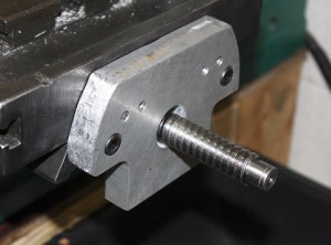
I cut out rough profiles of the endplates on the band saw from some 3/4″ 6061 aluminum stock I had on hand.  I used the original endplates as rough guides.   I did not machine the outer profile very carefully as I felt it was not important enough to justify the time.  I rough drilled the center hole, then marked the actual center by tracing the leadscrew.  A large endmill centered over the markings bored out the ballscrew opening.  This easily lined up the screw in the hole through the support piece.  I liked the idea of using dowel pins to maintain a fixed alignment of the end plates.  Transferring the dowel pins from the original  plates worked poorly so I  drilled and reamed new ones with over under reamers.


After mounting both end plates I focused on the stepper driven side as it would support the leadscrew in both an axial and radial fashion by using a 5202 double row angular contact bearing.   This end is critical as the 5202 bearing is designed to take the axial thrust loads during the operation of the cnc milling machine resulting in no backlash when changing directions.  I needed to machine a spacer for the 15 x 1.0mm bearing nut to tighten my anti-backlash ballscrew onto the 5202 bearing.  I also machined the bearing retention block.  This is just a 3/4″ thick aluminum square faced and bored to accept the 5202 bearing with 10-15 thousandths of the bearing sticking out.  The bore is machined 10 to 15 thousandths shallow so that when tightened down against the end plate the bearing will be held captive with no play in the axial direction.   Drilling and taping the bearing retaining block  in place was done very carefully by clamping down the table,  tightening the bearing hard against the end plate by turning the leadscrew, and carefully transferring, drilling, and tapping the 6mm threaded holes.   This way I was able to use the leadscrew to provide proper alignment of the bearing support block.  It required some careful hand work, but worked well in the end.

Anti Backlash ballscrew upgrade for CNC miling machine    Stepper drive mechanism with L series timing belt pulleys

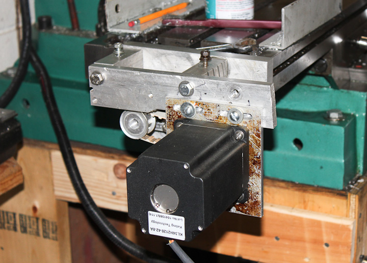
As this is CNC machine version 2.0  I decided to reuse much of my original mounting mechanism for the motor.  Originally I had relied on a clamp on mount from the original x axis drive that came with the ZAY7045 mill drill from lathemaster.com.   Version 2.0 would mount off of the end plate allowing me to sell the x axis drive motor and clear up much needed shelf space in the shop .   I am using L series timing belts tensioned by a slotted slide mechanism.   Another change from version 1.2  include a reduction in pulley ratio from 1:2 to 1:1 using 10 tooth L series timing pulleys (part number A 6A 4-10DF05016) from Stock Drive Products/Sterling Instrument  allowing for much higher rapid traverse speeds.  I did have to open up the bore on the pulley to 15mm from the 0.500″ inch stock bore.
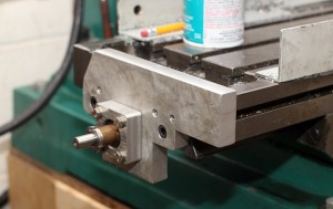
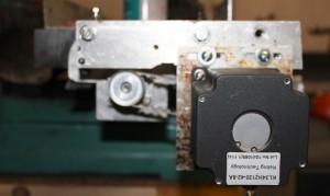
With this new ball screw the machine can move the x axis at speeds in the 30 ipm range as an upper limit.  The earlier version  had a max travel speed of only 8 IPM.  Mostly due to the motors not being able to drive the poor quality inefficient ACME leadscrew.  I plan to alter my motor configuration in the future to a direct drive set up with the motor coupled to the ballscrew via a zero backlash misalignment bushing.

Ballscrew replacement on RF45 clone CNC conversion   Anti Backlash ballscrew upgrade for CNC miling machine

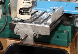
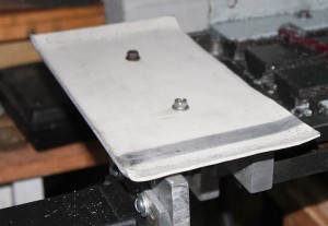
The last addition to the drive mechanism is a splash shield.  I use a flood coolant system for CNC milling, making a splash shield for the drive mechanism a must.  I bent and hammered out some 0.095″ Al sheet I had handy such that all of the edges are raised except where it floods back into the milling machine table resevoir.

My work is not done on this project but this post is for now. I carefully measured the other end of the antibacklash ballscrew.  I need to have the 15mm diameter bearing area of the screw (upper right photo at the end of the screw) extended to a length 77mm from this end of the ballscrew.  This is required to mount the other support bearing (6202) and the bearing retainer onto the end plate.  This side only supports the ballscrew in the radial direction and is less critical.  I plan to leave the 15mm dia section long so I can later add either a rotary encoder and/or a manual control handle.  In order to machine the leadscrew end I need to dissassemble the entire machine yet again, carefully remove the ball nut, and find someone with a lathe who is kind enough to help me out turning it down carefully.  Sadly, my 100 year old lathe is not up to the level of concentrically I need machined.
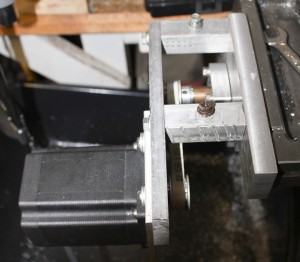
I have driven and tested this new ballscrew setup and it is vastly superior to the original ACME leadscrew.  Higher speeds will allow for faster machining times, especially on parts that have many non cutting rapid moves, such as drilling bolt patterns.  I realize now that I should have replaced the leadscrews years ago and that I now must do the Y axis.  Likely I will measure and get started on the Y axis upgrade when I disassemble and have the x axis anti-backlash ballscrew end machined.  I hope my work helps someone with their own conversion.  I looked hard to find details on what screw would fit, where to buy one, etc. without much success.